
Page 766 - 5G Basics - Core Network Aspects
P. 766
2 Transport aspects
where NRMC = floor(LRMC/8). The number of padding bits added after the user data bytes shall be equal to the
difference between the number of data bits modulated over user data tones (LDR) and the number of user
data bits (8 × BDR) with BDR=floor(LDR/8). Figure 10-3 (on the bottom) shows the RMC symbol structure.
The content of the padding bits is vendor discretionary. The values of LD, LR, and LDR shall accommodate
actual bit loading and trellis overhead, as defined in clause 10.2.1.3.
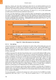
The order of the data extracted per symbol is presented in Figure 10-3 (shaded area shows padding bits).
For normal data frames, the symbol encoder shall first extract BD bytes from the incoming data frame and
then add (LD − 8×BD) padding bits. For RMC data frames, the symbol encoder shall first extract NRMC bytes
from the incoming data frame and add (LRMC − 8×NRMC) padding bits, and then it shall extract BDR more bytes
from the incoming data frame and add (LDR − 8×BDR) padding bits; the total number of bits LR = LRMC + LDR
and the total number of bytes BR = NRMC + BDR.
Figure 10-3 – Order of bit extraction from data frame
10.2.1.2 Tone ordering
During the initialization, the receive FTU shall calculate the number of bits and the relative gains to be used
for every subcarrier in the MEDLEY set during data symbols and RMC symbols (either MEDLEYus or
MEDLEYds, depending on the transmission direction), as well as the order in which subcarriers are assigned
bits (i.e., the tone ordering). The number of subcarriers in MEDLEYus and MEDLEYds is denoted by NSCus
and NSCds, respectively.
In addition, the receive FTU shall select the subcarriers used to encode the RMC during the RMC symbols.
The selected RMC tone set is denoted by RTSus and RTSds for upstream and downstream, respectively. The
number of subcarriers in the RMC tone set is denoted NSCRds and NSCRus for the downstream and upstream
directions, respectively. The tones from the RMC tone set are exclusively for RMC and shall not carry any
DTU bits. No subcarriers of the RMC tone set shall be loaded with 1-bit for RMC symbols or for data
symbols in the NOI in order to use the same re-ordered tone table for data symbols in the NOI and RMC
symbols. The RMC tone set may be modified in showtime through OLR. The FTU shall calculate the number
of bits and the relative gains to be used for every subcarrier in the RMC tone set during RMC symbols and
shall send them back to the transmit FTU during initialization. The bits and gains used to encode the
subcarriers not belonging to the RTS shall be the same for RMC and data symbols in the NOI.
The pairs of bits and relative gains used for data symbols are defined in ascending order of frequency or
subcarrier index i as a bit allocation table b and gain table g containing, respectively, bi and gi values for all
subcarrier indices i that belong to the MEDLEY set. The bit allocation table b shall include an even number
of 1-bit subcarriers (NCONEBIT).
The tone ordering table t is defined as the sequence {tk} in which subcarriers from the MEDLEY set shall be
assigned bits. Each value tk (for k = 1 to k = NSCus for the upstream tones, k = 1 to k = NSCds for the
756