
Page 687 - 5G Basics - Core Network Aspects
P. 687
Transport aspects 2
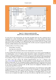
Figure 5-2 – Reference model of the DPU
(shown for line 1 of N lines connected to the DPU)
For each FTU-O in the vectored group, the data plane information flow over the γO reference point is
represented by a single downstream data stream (STREAMds-n) and a single upstream data stream
(STREAMus-n), where 'n' is an identifier for a specific FTU-O (FTU-O-n) and associated wire-pair. The FTU-O
may use flow control (TX Enable-n) on the downstream data stream. The L2+ entity may use flow control
(RX Enable-n) on the upstream data stream. Inside the DPU, the ME conveys the management information
(over the γ_MGMTO interface) to each of the FTU-Os.
The functionalities of the DPU also include:
• Timing control entity (TCE);
• Vectoring control entity (VCE);
• Dynamic resource allocation (DRA) that also includes power control entity (PCE).
The TCE coordinates the transmission and reception with synchronous time-division duplexing (STDD) over
the vectored group. At the U-O reference point, downstream symbols transmitted by all N FTU-Os,
upstream symbols transmitted by all N FTU-Rs, downstream sync symbols transmitted by all N FTU-Os, and
upstream sync symbols transmitted by all N FTU-Rs are aligned over all wire-pairs in the vectored group.
The coordination is shown in Figure 5-2 as the same TDD timing being passed from the TCE to all N FTU-Os.
The access node (AN) receives the network frequency/timing over the V reference point
(e.g., [b-ITU-T G.8264], [b-IEEE 1588]). The frequency/timing is conveyed through the OLT, ODN and PHY
and/or L2+ block to the TCE. The TCE passes the network timing reference (NTR) and time-of-day (ToD) to
all N FTU-Os. The TCE may synchronize the TDD timing (including the transceiver sample clock fs) to the NTR
or ToD reference frequency. Inside the DPU, the ME conveys the management information (over an
interface here called TCE-m) to the TCE.
The VCE coordinates the crosstalk cancellation over the vectored group. This coordination is made possible
through communication from each FTU-O to all other FTU-Os; for example ε-1-n identifies the interface
between an FTU-O on line 1 (here called FTU-O-1) and all other FTU-Os on lines n (here called FTU-O-n,
n=2…N). Coordination data (e.g., precoder data for vectoring) are exchanged between FTU-O-n1 and
FTU-O-n2 over an interface here called ε-n1-n2. Each VCE controls a single DPU, and controls FTU-O-n
677