
Page 686 - 5G Basics - Core Network Aspects
P. 686
2 Transport aspects
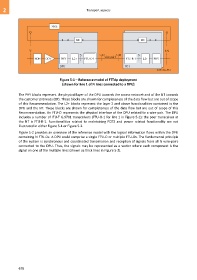
Figure 5-1 – Reference model of FTTdp deployment
(shown for line 1 of N lines connected to a DPU)
The PHY blocks represent the physical layer of the DPU towards the access network and of the NT towards
the customer premises (CP). These blocks are shown for completeness of the data flow but are out of scope
of this Recommendation. The L2+ blocks represent the layer 2 and above functionalities contained in the
DPU and the NT. These blocks are shown for completeness of the data flow but are out of scope of this
Recommendation. An FTU-O represents the physical interface of the DPU related to a wire-pair. The DPU
includes a number of ITU-T G.9701 transceivers (FTU-O-1 for line 1 in Figure 5-1); the peer transceiver at
the NT is FTU-R-1. Functionalities related to maintaining POTS and power related functionality are not
illustrated in either Figure 5-1 or Figure 5-2.
Figure 5-2 provides an overview of the reference model with the logical information flows within the DPU
containing N FTU-Os. A DPU could comprise a single FTU-O or multiple FTU-Os. The fundamental principle
of the system is synchronous and coordinated transmission and reception of signals from all N wire-pairs
connected to the DPU. Thus, the signals may be represented as a vector where each component is the
signal on one of the multiple lines (shown as thick lines in Figure 5-2).
676