
Page 1216 - 5G Basics - Core Network Aspects
P. 1216
2 Transport aspects
ODTUk.ts overhead
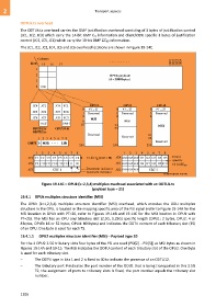
The ODTUk.ts overhead carries the GMP justification overhead consisting of 3 bytes of justification control
(JC1, JC2, JC3) which carry the 14-bit GMP Cm information and client/ODU specific 3 bytes of justification
control (JC4, JC5, JC6) which carry the 10-bit GMP C8D information.
The JC1, JC2, JC3, JC4, JC5 and JC6 overhead locations are shown in Figure 19-14C.
Column
Row 15 16 17 3821 3822 3823 3824
1
2 OPUk payload
3 (4 3808 bytes)
4 PSI
JC4 JC1 JC4 JC1 OPU2 OPU3 OPU4
0 PT = 21 0 PT = 21 0 PT = 21
JC5 JC2 JC5 JC2
1 Reserved 1 Reserved 1 Reserved
JC6 JC3 JC6 JC3 2 MSI 2 2
9 MSI
RES OMFI 10 33 MSI
ODTU2.ts ODTU4.ts 34
ODTU3.ts
Reserved 81
1 2 3 4 5 6 7 8 Reserved 82
Reserved
OMFI 0 MSB LSB
255 255 255
1 2 3 4 5 6 7 8 1 2 3 4 5 6 7 8
JC1 C1 C2 C3 C4 C5 C6 C7 C8 14-bit C (m=8 M) JC4 RES RES RES D1 D2 D3 D4 D5 Client
m
specific
JC2 C9 C10 C11 C12 C13 C14 II DI JC5 RES RES RES D6 D7 D8 D9 D10
10-bit C 8D
JC3 CRC-8 Decrement indicator JC6 RES RES RES CRC-5
Increment indicator
G.709-Y.1331(12)_F19-14C
Figure 19-14C – OPUk (k=2,3,4) multiplex overhead associated with an ODTUk.ts
(payload type = 21)
19.4.1 OPUk multiplex structure identifier (MSI)
The OPUk (k=1,2,3,4) multiplex structure identifier (MSI) overhead, which encodes the ODU multiplex
structure in the OPU, is located in the mapping specific area of the PSI signal (refer to Figure 19-14A for the
MSI location in OPUk with PT=20, refer to Figures 19-14B and 19-14C for the MSI location in OPUk with
PT=21). The MSI has an OPU and tributary slot (2.5G, 1.25G) specific length (OPU1: 2 bytes, OPU2: 4 or
8 bytes, OPU3: 16 or 32 bytes, OPU4: 80 bytes) and indicates the ODTU content of each tributary slot (TS)
of an OPU. One byte is used for each TS.
19.4.1.1 OPU2 multiplex structure identifier (MSI) – Payload type 20
For the 4 OPU2 2.5G tributary slots four bytes of the PSI are used (PSI[2] .. PSI[5]) as MSI bytes as shown in
Figures 19-14A and 19-15. The MSI indicates the ODTU content of each tributary slot of the OPU2. One byte
is used for each tributary slot.
– The ODTU type in bits 1 and 2 is fixed to 00 to indicate the presence of an ODTU12.
– The tributary port # indicates the port number of the ODU1 that is being transported in this 2.5G
TS; the assignment of ports to tributary slots is fixed, the port number equals the tributary slot
number.
1206