Page 1005 - 5G Basics - Core Network Aspects
P. 1005
Transport aspects 2
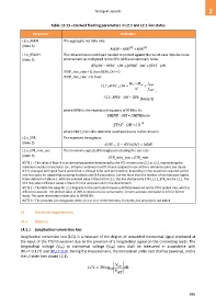
Table 13-13 – Derived framing parameters in L2.1 and L2.2 link states
Parameter Definition
L2.x_ANDR The aggregate net data rate:
(Note 3) DS US
ANDR NDR NDR
L2.x_RTxOH The retransmission overhead needed to protect against the worst-case impulse noise
(Note 3) environment as configured in the DPU-MIB and stationary noise.
RTxOH REIN _ OH SHINE_ OH STAT _ OH
If INP_min_rein = 0, then REIN_OH = 0
If INP_min_rein > 0, then:
M M f
L 1.2 : REIN _ OH F SF REIN
N f DMT ,
: 2 . 2 L REIN _OH 20 %
(Note 2)
where fREIN is the repetition frequency of REIN in Hz.
SHINE_ OH SHINEratio
STAT _OH 10 4
where STAT_OH is the statistical overhead due to retransmission
L2.x_ETR The expected throughput:
(Note 3) ETR 1( RTxOH ) NDR
L2.x_ETR_min_eoc The minimum expected throughput including the eoc rate:
(Note 3)
ETR_min_eoc = ETR_min
NOTE 1 – The value of Beoc-R is an internal parameter determined by the VCE at entry into L2.1 or L2.2, representing the
maximum number of eoc bytes (i.e., all bytes contained in a DTU frame assigned to eoc at the reference point, see clause
8.3.1) averaged per logical frame period that is allowed to be sent per direction, depending on the maximum required eoc bit
rate necessary for supporting vectoring feedback and OLR procedures, but not more than the number of eoc bytes per logical
frame defined in Table 6-1. With the selected value of Beoc-R for L2.1, the line shall provide ETR ≥ L2.1_ETR_min for L2.1. The
VCE may select different values of Beoc-R in the upstream and in the downstream.
NOTE 2 – The REIN-OH value for L2.2 depends on the particular frequency shifts between AC and G.9701 symbol rate, which is
difficult to account. The defined value of 20% is expected to be conservative. A more accurate estimation is left for further
study. The same reservation relates also to SHINE-OH.
NOTE 3 – The prescript L2.x designates either L2.1 or L2.2. In the formulas, for clarity, the prescript is not added.
14 Electrical requirements
14.1 Balance
14.1.1 Longitudinal conversion loss
Longitudinal conversion loss (LCL) is a measure of the degree of unwanted transversal signal produced at
the input of the FTU transceiver due to the presence of a longitudinal signal on the connecting leads. The
longitudinal voltage (Vcm) to transversal voltage (Vdiff) ratio shall be measured in accordance with
[ITU-T G.117] and [ITU-T O.9]. During the measurement, the transceiver under test shall be powered, and in
the L3 state (see clause 12.1).
V
LCL 20 log 10 cm dB
V diff
995

