
Page 1004 - 5G Basics - Core Network Aspects
P. 1004
2 Transport aspects
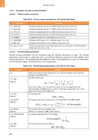
13.4.4 Low power link state control parameters
13.4.4.1 Primary control parameters
Table 13-12 – Primary control parameters in L2.1 and L2.2 link states
Parameter Definition
L2.1_NDR_max Maximum allowed value for L2.1_NDR in kbit/s (see clause 13.4.1.5.2).
L2.2_NDR_max Maximum allowed value for L2.2_NDR in kbit/s (see clause 13.4.2.5.2).
L2.1_ETR_min Minimum allowed value for L2.1_ETR in kbit/s (see clause 13.4.1.5.1).
L2.2_ETR_min Minimum allowed value for L2.2_ETR in kbit/s (see clause 13.4.2.5.1).
L2_TARSNRM Target SNR margin in L2 in dB (see clause 13.4.1.5.3).
L2.1_MAXSNRM Maximum SNR margin in L2.1 in dB (see clause 13.4.1.5.4).
L2_PSDR_max Maximum PSD reduction in L2 in dB (see clause 13.4.1.5.5).
L2.1_Exit_ETR_min Minimum expected ETR upon returning from the L2.1 link state to the L0 link state, in
kbit/s (see clause 13.4.1.5.6).
13.4.4.2 Derived framing parameters
Derived framing parameters can be computed using the primary parameters as input. The derived
parameters can be used to verify data rates or to identify additional constraints on the validity of the
primary parameters. The derived parameters defined in Table 13-13 utilization L2.1 and L2.2 transmission
formats defined in clause 13.4.1 and clause 13.4.2, respectively.
Table 13-13 – Derived framing parameters in L2.1 and L2.2 link states
Parameter Definition
fDMT Symbol rate of transmission expressed in Hz as specified in clause 10.4.4 (same for
upstream and downstream).
L2.x- f RMC The RMC symbol rate:
(Note 3) 1 N 1
f RMC f DMT
M F M SF X
where N (see clause 13.4.1.1) and X (see clause 13.4.2.1) are parameters that
determine RMC schedule during L2.1 and L2.2 link states, respectively. For L2.1 link
state, X=1 and for L2.2 link state, N=1.
L2.x_DPR DTU payload rate:
(Note 3) DPR DPR DR
L2.x_DPRDR DTU payload rate part corresponding to the data portion of the RMC symbol:
(Note 3) K
DPR DR 8( B ) f RMC FEC 1 DTUframing OH
DR
N FEC
L2.x_DPReoc DTU payload rate corresponding to eoc:
(Note 3) DPReoc = ( 8 × Beoc-R ) / (MF / fDMT ) (Note 1)
L2.x_DTUframingOH The relative overhead due to DTU framing:
(Note 3) 7
DTUframing OH
Q K FEC
L2.x_NDR The net data rate (for each direction):
(Note 3)
NDR DPR DPR eoc ,
994