
Page 94 - ITU Kaleidoscope 2016
P. 94
Antenna
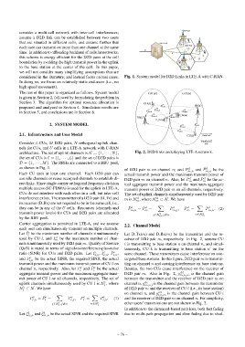
consider a multi-cell network with inter-cell interferences;
assume a D2D link can be established between two users RRH
that are situated in different cells, and assume further that BBU Pool CU
BS D2D Pair RRH
each user can transmit on more than one channel at the same D_Rx
S1
time. In addition to offloading backhaul of cellular networks, Ir D_Tx
this scheme is energy efficient for the D2D pairs at the cell
RRH
boundaries by avoiding the high transmit power in the uplink
to the base station at the center of the cell. In this paper,
we will not consider many simplifying assumptions that are
considered in the literature; and instead focus on real cases. Fig. 1. System model for D2D Links in LTE-A with C-RAN.
In doing so, we focus on relatively static end-users (i.e., no
high speed movement).
The rest of this paper is organized as follows. System model Cell ( )u Cell ( )u
is given in Section 2, followed by formulating the problem in
Section 3. The algorithm for optimal resource allocation is CU( )k cc
proposed and analyzed in Section 4. Simulation results are cd g kn ,,l BS( )u
g cc g kn ,,m g dc
in Section 5, and conclusions are in Section 6. kn ,,k mn ,,l
g dc g dd D_Tx(m)
BS( )u mn ,,k mnm
,,
D_Rx(m)
2. SYSTEM MODEL g cd ln ,,m g ln cc ,,l
g ln cc ,,k
2.1. Infrastructure and User Model CU( )l Data link
Interference
Consider L CUs, M D2D pairs, N orthogonal uplink chan- link
nels for CUs, and U cells in a LTE-A network with C-RAN
architecture. The set of uplink channels is N = {1, · · · , N}, Fig. 2. D2D links underlaying LTE-A network.
the set of CUs is C = {1, · · · , L} and the set of D2D pairs is
D = {1, · · · , M}. The RRHs are connected to a BBU pool,
as shown in Fig. 1. d ¯ d
of D2D pair m on channel n; and P m,n and P m,n be the
Each CU uses at least one channel. Each D2D pair can actual transmit power and the maximum transmit power of
use idle channels or reuse occupied channels to establish di- D2D pair m on channel n. Also, let P m and P ¯ d be the ac-
d
m
rect links. Since single-carrier orthogonal frequency-division tual aggregate transmit power and the maximum aggregate
multiple access (SC-FDMA) is used for the uplink in LTE-A, transmit power of D2D pair m on all channels, respectively.
CUs do not interfere with each other in a cell, but inter-cell The set of uplink channels simultaneously used by D2D pair
d
interference exists. The transmitter of a D2D pair (D Tx) and m is N , where N m ⊂ N. We have
d
m
its receiver (D Rx) are not required to be in the same cell, i.e.,
X X
d
d
¯ d
d
they can be in any of the U cells. Resources (channels and P ¯ d = P − P m,j , P m = P m,n . (2)
m
m,n
transmit power levels) for CUs and D2D pairs are allocated d n∈N d
j∈N m ,j6=n m
by the BBU pool.
Carrier aggregation is permitted in LTE-A, and we assume
2.2. Channel Model
each user can simultaneously transmit on multiple channels.
¯ c
Let I be the maximum number of channels simultaneously Let D Tx(m) and D Rx(m) be the transmitter and the re-
l
used by CU l, and I ¯ d be the maximum number of chan- ceiver of D2D pair m, respectively. In Fig. 2, assume CU
m
nels simultaneously used by D2D pair m. Quality of Service l is transmitting to base station u on channel n, and simul-
0
(QoS) is stated in terms of signal-to-interference-plus-noise taneously, CU k is transmitting to base station u on the
ratio (SINR) for CUs and D2D pairs. Let ξ c , ξ ˆ c , P c , same channel. These transmitters cause interference on non-
l,n l,n l,n
and P ¯ c be the actual SINR, the required SINR, the actual targeted base stations. In this figure, D2D pair m is transmit-
l,n
transmit power and the maximum transmit power of CU l on ting on channel n and causing interference on base stations.
¯ c
c
channel n, respectively. Also, let P and P be the actual Besides, the two CUs cause interference on the receiver of
l l
aggregate transmit power and the maximum aggregate trans- D2D pair m. Also in Fig. 2, g dd is the channel gain
m,n,m
mit power of CU l on all channels, respectively. The set of between the transmitter and the receiver of D2D pair m on
dc
c
uplink channels simultaneously used by CU l is N , where channel n, g m,n,l is the channel gain between the transmitter
l
c
N ⊂ N. We have of D2D pair m and the receiver of CU l (i.e., its base station)
l
on channel n, and g cd is the channel gain between CU l
X c c X c l,n,m
¯ c
P ¯ c = P − P , P = P l,n . (1) and the receiver of D2D pair m on channel n. For simplicity,
l,n
l
l
l,j
c
j∈N l ,j6=n n∈N c other users’ transmissions are not shown in Fig. 2.
l
In addition to the distanced-based path loss, both fast fading
d
Let ξ m,n and ξ ˆ d be the actual SINR and the required SINR due to multi-path propagation and slow fading due to shad-
m,n
– 76 –