
Page 62 - Kaleidoscope Academic Conference Proceedings 2024
P. 62
2024 ITU Kaleidoscope Academic Conference
2. THE HONG-OU-MANDEL EXPERIMENT channels coming from Alice and Bob. Further, a polarization
controller (PC) is used to control the required polarization
Here, the aim is to perform HOM experiment between the state. One arm of the both PBSs (Alice’s as well as Bob’s)
photons generated from two parties named as Alice and Bob. is connected to a single photon avalanche diode (SPAD3 and
Alice and Bob use attenuated independent laser sources for SPAD4). The minimum clicks on both the SPADs indicate
this purpose. This is done using an intensity modulator that the photons on the other arm of PBS are nearly identical in
(IM) and variable optical attenuator (VOA). They send their polarization degree of freedom. This arm is in turn connected
photons to a third party, Charlie for Bell state measurement, to a 2 x 2 polarization maintaining beam splitter (PMBS)
as shown in Fig. 2. To obtain indistinguishability, we have which is then connected to two SPADs (SPAD1 and SPAD2)
maintained three feedback mechanisms between Alice, Bob of which one is free running SPAD and the other is a gated
and Charlie namely frequency overlap, polarization overlap SPAD as shown in Fig. 4.
and temporal overlap which is explained in detail.
2.3 Temporal overlap
2.1 Frequency overlap
The next challenge to make photons indistinguishable is their
In our experimental setup, Alice and Bob use 10% of their temporal overlap. The photons from both the sources must
laser light to achieve frequency overlap, the rest 90% they meet at the same time at Charlie’s node. Charlie measures
use for the HOM experiment implementation. The incoming the time of arrival of photons from Alice and Bob at a fixed
unmodulated continuous laser light (10%) from Alice and point. It is done in two steps:
Bob is fed to 2 x 1 optical coupler at Charlie node. The
• Delay calculation of photon from Alice and Bob to
output of the coupler is then fed to optical to electrical
PMBS.
(O2E) converter which is processed by the Charlie’s field
programmable gate array (FPGA). Whenever the frequency • Offset in SPADs after PMBS.
difference f is greater than the threshold frequency of 10 MHz,
The delay in the arrival of the photon is calculated by
it is communicated to Alice via the feedback channel and its
Charlie’s FPGA, and the corresponding shift is communicated
laser wavelength is tuned as shown in Fig. 3. In this way,
to any one of the two parties. In our work, the delay is
frequency overlap is achieved which is a very important step
adjusted at Bob node. The time shift is provided through
to make photons indistinguishable.
FPGA in the resolution of 125 ps. The concept of photon
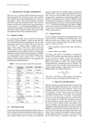
Table 1 – Various parameters used in the experiment indistinguishability is quantified in terms of visibility. The
visibility measures the probability that both photons will
S. No. Parameter Alice Value Bob Value emerge together through a single output port of the BS.
Transmitted Mathematically, the visibility is defined as
1 Power -78.8dBm -78.3dBm
Central −
2 Wavelength 1550.12 nm 1550.12 nm = (2)
Pulse
Repitition
where Cmax and Cmin are the maximum and minimum
3 Rate 32 ns 32 ns
Fibre coincidence counts at the output of the BS respectively.
4 Length 20 km 20 km
Fibre 3. RESULTS AND DISCUSSION
5 Loss 5 dB 5 dB
PC When the temporal, spectral and polarization overlap of the
Insertion
6 Loss 0.8 dB 0.8 dB photons on the Charlie’s BS is perfect, the two photons will
PBS exit the BS together in the same output port. There is zero
Insertion probability that both of the photons will exit separately. In
7 Loss 0.8 dB 0.8 dB our experiment, we have used two lasers of 1550.12 nm
Power at
the input of wavelength, having a pulse width of 880 ps with a repetition
8 2 x 2 PMBS -85.4 dBm -84.9 dBm rate of 32 ns (shown in Fig. 5 and Fig. 6 respectively).
Mean Photon The power of the pulse generated by laser sources present
number at the in Alice and Bob is 78.8 dBm and 78.3 dBm respectively,
input of
the other parameters are given in the Table I. Fig. 7 shows
9 2 x 2 PMBS 0.72 0.8
the clicks on the two SPADs (SPAD1 and SPAD2) out of
which one (SPAD1, blue colored line) is in the free running
2.2 Polarization overlap configuration which has high click count and the other one
(SPAD2, red colored line) is in gated mode which has low
To make both photons indistinguishable at Charlie’s node, one click count. Free running detector triggers (gates) the second
of the conditions is that their polarization should be same. In detector. Fig. 8 shows the coincidence counts with respect
order to achieve the same, we make use of two polarizing to time difference between two pulses, as the time between
beam splitters (PBSs) which are inserted on the quantum the two pulses reduces, coincidence count reduces. The
– 18 –