
Page 1334 - 5G Basics - Core Network Aspects
P. 1334
2 Transport aspects
messages) are inserted into the OSMC at the earliest opportunity. GFP Idle frames may be inserted
between successive GFP frames.
The mapping of generic framing procedure (GFP) frames is performed by aligning the byte structure of
every GFP frame with the byte of the OSMC overhead field. Since the GFP frames are of variable length and
may be longer than 16 bytes, a GFP frame may cross the FlexO multi-frame boundary.
9.2.10.1 Generation of event message timestamp
The message timestamp point [ITU-T G.8260] for a PTP event message transported over the OSMC shall be
the 32-frame multi-frame event (corresponding to MFAS[4:8] = 00000) preceding the beginning of the GFP
frame, in which the PTP event message is carried. Since the GFP frames may be longer than 64 bytes, a
frame may cross the FlexO 32-frame multi-frame boundary.
All PTP event messages are timestamped on egress and ingress interfaces. The timestamp shall be the time
at which the event message timestamp point passes the reference plane [ITU-T G.8260] marking the
boundary between the PTP node (i.e., OTN node) and the network.
Event message timestamps are generated at the FlexO Access Point. The message timestamp point is
specified below as the 32-frame FlexO multi-frame event corresponding to MFAS[4:8] = 00000. For this
application, the FlexO multi-frame event is defined as when the first bit of the first alignment marker,
corresponding to MFAS[4:8] = 00000 frame, on a lane crosses between the PTP node (i.e., OTN node) and
the network (i.e., the analogous point to Ethernet MDI). In the case of a multi-lane PHY, the PTP path data
delay is measured from the beginning of the alignment marker at the reference plane, which is equivalent
to Ethernet MDI of the lane with the maximum media propagation delay. In practice:
– On egress interfaces, since the alignment markers for all lanes are transmitted at the same time
conceptually, any alignment marker can be used for timestamping.
– On ingress interfaces, alignment markers are present in all the lanes, but different lanes may be
skewed from each other. The last received alignment marker across all the lanes shall be used for
timestamping.
NOTE 1 – The first byte of a GFP (PTP event message) frame is inserted into the FlexO OSMC between 4 and 31 frames
after the 32-frame multi-frame boundary.
NOTE 2 – The guard band of four frames is defined to simplify implementation.
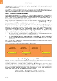
Figure 9-10 Timing diagram example for OSMC
NOTE 3 – This time synchronization over FlexO interface implementation does not generate event message
timestamps using a point other than the message timestamp point [ITU-T G.8260].
In this time synchronization over FlexO interface implementation, the timestamps are generated at a point
removed from the reference plane. Furthermore, the time offset from the reference plane is likely to be
different for inbound and outbound event messages. To meet the requirement of this subclause, the
generated timestamps should be corrected for these offsets. Figure 19 in [IEEE 1588] illustrates these
offsets. Based on this model, the appropriate corrections are as follows:
<egressTimestamp> = <egressMeasuredTimestamp> + egressLatency
<ingressTimestamp> = <ingressMeasuredTimestamp> – ingressLatency
1324