
Page 80 - ITU Journal Future and evolving technologies Volume 2 (2021), Issue 7 – Terahertz communications
P. 80
ITU Journal on Future and Evolving Technologies, Volume 2 (2021), Issue 7
28 28
0 28 0 28 0.5 26 0.5 26
26
26
0.5 0.5 24 24
1 1
24
24
1 1 22 22
Width (m) 1.5 22 20 Width (m) 1.5 22 20 Width (m) 1.5 20 Width (m) 1.5 20
2 2 2 18 2 18
18 18
2.5 2.5 16 16 16
16 2.5 2.5
3 14 3 14 14 14
0 0.5 1 1.5 2 2.5 3 3.5 4 4.5 5 0 0.5 1 1.5 2 2.5 3 3.5 4 4.5 5 0.5 1 1.5 2 2.5 3 3.5 4 4.5 0.5 1 1.5 2 2.5 3 3.5 4 4.5
Length (m) Length (m) Length (m) Length (m)
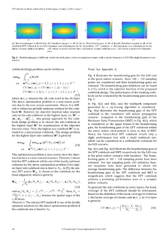
(a) Beamforming gain in dB of the hi‑ (b) Beamforming gain in dB of the (c) Beamforming gain in dB of the (d) Beamforming gain in dB of the
erarchical DFT codebook in the LOS maximum ratio transmission in the hierarchical DFT codebook in the maximum ratio transmission in the
indoor scenario without furniture. LOS indoor scenario without furni‑ LOS indoor scenario with furniture. LOS indoor scenario with furniture.
ture.
Fig. 4 – Beamforming gain of different codebooks in the given indoor propagation scenario with a carrier frequency of 100 GHz single‑frequency trans‑
mission.
codebook design problem can be written as A.
2
max W ∫ (Φ) Φ Fig. 4 illustrates the beamforming gain for the LOS case
Φ=0 in the given indoor scenario. Here, 100 × 100 sampling
s.t. w ( , )w( , ) = 1, 1 ≤ ≤ , 1 ≤ ≤ 2 −1 points are considered and their beamforming gains are
obtained. The beamforming gain de inition can be found
(w( , )) = (w( + 1, 2 − 1))∪
in (11), which is the objective function of the proposed
(w( + 1, 2 )), 1 ≤ ≤ − 1, 1 ≤ ≤ 2 −1 , codebook design. The performance of the resulting code‑
(13) book can be evaluated by the beamforming gain shown in
where w( , ) denotes the th code word in the th layer. Fig. 4.
The above optimization problem is a non‑convex prob‑
lem due to the non‑convex constraints. Hence, it is dif i‑ In Fig. 4(a) and 4(b), only the multipath component
cult to obtain the globally optimum solution for the code‑ generated by a ray‑tracing algorithm is considered.
book W. However, the objective function value depends Fig. 4(a) illustrates the beamforming gain of the DFT
only on the sub‑codebook in the highest layer, i.e., W = codebook in the considered LOS indoor propagation
[w , w , ⋯ , w −1 ]. One greedy approach for the code‑ scenario. Compared to the beamforming gain of the
2
1
2
book design problem is to choose the sub‑codebook in Maximum Ratio Transmission (MRT) in Fig. 4(b), which
the highest layer W for maximization of the objective is considered as the upper bound of the beamforming
function value. Then, the highest sub‑codebook W is ex‑ gain, the beamforming gain of the DFT codebook within
tended to a hierarchical codebook. The design problem the entire indoor environment is close to that of MRT.
for the highest layer sub‑codebook W is given by Hence, the hierarchical DFT codebook entails only a
slight performance loss with a small codebook size,
2
max W ∫max w∈W ‖a ( , )w‖ which can be considered as a welltailored codebook for
2
(14) the LOS scenario.
s.t. w ( , )w( , ) = 1, 1 ≤ ≤ 2 −1 . Fig. 4(c) and Fig. 4(d) illustrate the beamforming gain of
the DFT codebook and MRT, respectively, for the LOS case
This optimization problem is non‑convex since the objec‑
in the given indoor scenario with furniture. The beam‑
tive function is a non‑concave function. Theorem 1 shows forming gains of 100 × 100 sampling points have been
that the DFT codebook will be one of the locally optimum obtained. For one sampling point, 100 statistical chan‑
solutions for the above optimization problem if the high‑
nel snapshots have been generated to obtain the
est layer sub‑codebook size is ixed to . In [9], the uni‑ average beamforming gain. The difference between the
tary DFT matrix W is chosen as the codebook for the
beamforming gain of the DFT codebook and MRT is
beam alignment, which is given by
insignificant, which suggests that the DFT codebook
1 achieves a promising performance even in a complex
W = [a ( , Φ ), ⋯ , a ( , Φ ), ⋯ , a ( , Φ )],
√
1 indoor scenario.
(15) To generate the sub‑codebooks in lower layers, the beam
with a ( , Φ ) = [1, Φ , ⋯ , ( −1)Φ ] . Here, Φ = coverage of the DFT codebook should be determined.
(2 −1) Based on the de inition of the beam coverage in Criterion
, ∈ {1, ⋯ , } denotes the spatial angle of the
1, the beam coverage of a beam code w( , ) in t h layer
‑th beam.
is given by
Theorem 1: The unitary DFT matrix F is one of the locally
optimum solutions for the above optimization problem if 2 ( − 1) 2
the codebook size is ixed to (w( , )) = ( , ) . (16)
68 © International Telecommunication Union, 2021