
Page 52 - Kaleidoscope Academic Conference Proceedings 2020
P. 52
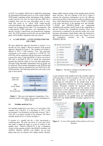
in STEP. For example, JSDAI can be applied for integrating   planar enables motion settings of the machine parts with the
           the information from both sources to create a final complete   same  reference.  The  tree  structure  to  the  left  in  Figure  4
           STEP model containing all the information of the machine   contains  the  kinematics  information  on  how  the  different
           model from the CAx tool. To ensure that the STEP file is   parts and assemblies of the machine model are related to each
           complete,  there  may  be  extra  information  such  as  users’   other, which determines how they move. HURCO_VM10UI
           input  that  needs  to  be  added.  With  vendor-specific   is the name and model of the machine tool, and FRAME,
           converters/adapters, the complete machine model in STEP   Y_SLIDE   and   SPINDLE_HEAD   are   components
           format can be imported into other CAx environments. The   constituting the machine model. Each of the components in
           vendor-specific  STEP  generators  vary  depending  on  the   the  tree  structure  has  a  breakdown  structure  where  more
           specific interface requirements and programming language   information is contained for the machine model, such as the
           used. The STEP generator used for the case presented in this   kinematic information, which defines either the rotational or
           paper will be further explained in the next section.    translational movement in the x- and y-axis. Figure 5 shows
                                                              the   breakdown   structure   for   the   component
            4.  A CASE STUDY – A STEP GENERATOR FOR           SPDINLE_HEAD.
                                PTC CREO

           We have applied the approach described in Section 3 to a
           specific use case. Figure 3 shows an instance of the general
           approach depicted in Figure 2. The machine tool model is
           defined  in  PTC’s  CAD  software,  Creo.  The  geometric
           information of the  model is  exported to a STEP file. The
           STEP file will be integrated with the kinematics information
           generated by using J-Link and JSDAI. J-Link is a Java-based
           API  that  is  provided  by  PTC  to  enable  the  interactions
           between the machine model in Creo and other applications.
           Through J-link, kinematics information from the model can
           be extracted. The geometric information in the STEP file and
           the kinematics data are integrated into one STEP file by the
           STEP generator. The following subsections will explain each   Figure 4 – The Hurco machine tool model in Creo
           step in more details.                                                  Parametric


                                                              A representation of the spindle head of the machine (marked
                                                              with green lines) is shown in Figure 5. The tree structure of
                                                              the  spindle  head  is  expanded  in  the  list  to  the  left,
                                                              representing  the  information  for  the  spindle  head,  which
                                                              includes  kinematics  information  about  the  alignment  and
                                                              rotation.  Placement  contains  the  kinematic  data  with
                                                              information  of  the  axis  alignment  and  the  rotation  of  the
                                                              spindle head. A tool is attached in the spindle head and the
                                                              rotational  movement  determines  how  material  is  removed
                                                              during  machining.  DEFAULT_CSYS  is  the  coordination
             Figure 3 – The case study approach: integrating a Creo   system  defined  for  the  spindle  head  and  ASM_RIGHT,
            machine model’s kinematics and geometric information in   ASM_TOP, and ASM_FRONT are planes applied for this
                              STEP AP242                      machine part.

           4.1    Machine model in Creo

           The machine model in the case study is a 5-axis Hurco CNC
           machine  tool,  VM10UI.  It  is  developed  in  PTC’s  CAD
           environment, Creo Parametric professional version 6. The J-
           Link API is an add-on module of the software. The Hurco
           machine model in Creo is shown in Figure 4.

           It  consists  of  a  spindle  and  the  y  slide  representing  a   Figure 5 – A view of the spindle of the machine and its tree
           machining table. The table can move in x-axis and y-axis,               structure
           and  rotate  to  adjust  the  angle  of  a  part  in  relation  to  the
           spindle  head.  VM10UI_MAINCYS  is  the  coordination
           system for the machine model of the HURCO machine, and
           ADTM1,  ADTM2,  ADTM3,  and  ADMT4  are  the  four
           planes that serve as reference for a planar surface. Defined


                                                           – xlviii –