
Page 196 - Proceedings of the 2017 ITU Kaleidoscope
P. 196
2017 ITU Kaleidoscope Academic Conference
" " "
!
" " " " " "
" " "
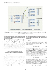
Fig 1. A block diagram of proposed MRC scheme for heterogeneous wireless networks consisting of a source and a
destination in the face of an eavesdropper
sults show that proposed MRC scheme performs better than path loss. Finally, all channels are assumed to encounter the
conventional MRS scheme in terms of their secrecy capacity zero-mean additive white Gaussian noise (AWGN) with a
and intercept probability. variance of N 0 .
The reminder of this paper is summarized as follows. Sec-
tion II shows the system model of heterogeneous wireless 2.2. MRS Scheme
networks and proposes the MRC scheme. For comparison
purposes, the conventional MRS scheme is also presented in In this section, we analyze the secrecy capacity of MRS
this section. Also, we characterize the secrecy capacity and scheme. The received signal at D for the i-th (i =1, 2,... N)
IP of both MRS and MRC schemes. Furthermore, in Section mode is expressed as
III, we present the proof of an absolute security with zero
y id = k i h i x + n d , (1)
intercept probability for the proposed MRC scheme. Nex-
t, numerical and simulation results are shown in Section IV. where h i is the fading coefficient of the S-D channel in the
Finally, Section V gives some concluding remarks. i-th mode, x is the signal to be transmitted by S, n d is the
2
2 d
AWGN encountered by D, k i = G r G s λ i −n i , G s and
(4π)
2. MULTI RADIO COOPERATION IN G r are the antenna gains of transmit and receive power, re-
HETEROGENEOUS WIRELESS NETWORKS spectively; λ i represents the wavelength of signal in the i-th
mode, d represents the distance between devices, and n i is
2.1. System Model the path loss factor in the i-th mode. Meanwhile, The re-
ceived signal at E for the i-th mode is expressed as
Fig. 1 shows a block diagram of proposed MRC scheme
y ie = k i g i x + n e , (2)
for heterogeneous wireless networks consisting of a source
(S) and a destination (D) in the face of an eavesdropper (E),
where g i is the fading coefficient of the S-E channel in the
each equipped with multiple heterogeneous radio access in-
i-th mode, and n e is the AWGN encountered by E. Accord-
terfaces, where N denotes the number of radio modes. The
ing to Shannon’s formula and combining (1) with (2), the
total transmit power is set to P, which means the signal trans-
capacity of main channel (from S to D) and wiretap channel
missions of the N radio modes share the total power P at one
(from S to E) in the i-th mode can be written as
time slot. Additionally, all the channels of Fig. 1 are modeled
2
as the Rayleigh fading with the consideration of large-scale C id =log (1 + γ|k i h i | ) (3)
2
– 180 –