
Page 91 - ITU-T Focus Group IMT-2020 Deliverables
P. 91
ITU-T Focus Group IMT-2020 Deliverables 3
NOTE 2 – Other reference points may be considered.
NOTE – Load rebalancing and load migration across network function instances assumes multiple active
instances of a network function. Potential issues resulting from load rebalancing and load migration to be
addressed may include:
– UE signalling overhead.
6.1.1.3 Architecture(s) for the Next Generation System
An agreement is as follows (excerpt from TR 23.799. please verify all specifics with 3GPP documents
necessarily. for example, architecture principles, non-roaming reference architecture, roaming reference
architectures, reference points and functionality description, and so on):
1) In Rel-15, AMF and SMF functions should be standardized as separate functions with standardized
interactions.
2) NAS MM and SM protocol messages terminate in AMF and SMF respectively. This is independent of
whether SM protocol terminates in the H-SMF or V-SMF.
3) NAS SM messages are routed by AMF.
4) Subscription profile data in NextGen is managed according to a user data convergence approach:
– A common user data repository (UDR) stores the subscription data, and this can be present
within the UDM.
– UDM Front End and PCF have access to this common UDR by implementing application Front
Ends to access relevant subscription data.
NOTE 1 – The terminology used above corresponds to the user data convergence approach defined
in EPC UDC architecture in TS 23.335.
NOTE 2 – The application logic of UDM Front End, e.g. for location management and subscription
update notification, as well as the application logic of PCF is to be further detailed during normative
phase.
5) The SEAF and SCMF are supported by the AMF.
6) The AUSF is defined as a separate NF.
7) Each NF can interact with each other directly.
8) The architecture does not describe an intermediate function between control plane functions but it
does not preclude the use of an intermediate function for routing and forwarding of messages
(e.g., like a DRA) between control plane functions, which may be identified for specific cases in the
deployments and should not require further work in stage 2.
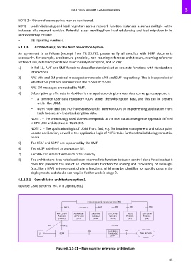
6.1.1.3.1 Consolidated architecture option 1
(Source: Cisco Systems, Inc., ATT, Sprint, etc.)
Figure 6.1.1-11 – Non-roaming reference architecture
85