
Page 84 - ITU-T Focus Group IMT-2020 Deliverables
P. 84
3 ITU-T Focus Group IMT-2020 Deliverables
5) If the UE is not suitably handled by the (Default) Front-end where the Attach Request was routed
to, this front end requests to assign the UE to a new front end that is more optimal (or less loaded)
for the selected slices. Then, it forwards the attach request to it with an indication it is a forwarded
attach and the IMSI and MDD indicated are respectively validated and already reflecting the Slice
Assignment at step 4. If not this step is skipped and the procedure continues from step 7.
6) The Selected front end binds itself to the selected slices for the UE and then sends back the
Forwarded Attach Accept message with Temporary ID and the accepted MDD for subsequent Usage
by the UE.
7) If the steps 5 and 6 were executed, the (Default) Handler sends to the RAN the Attach Accept in a
NAS message with the content copied from the message in step 6. Otherwise the (Default) Handler
binds itself to the selected slices for the UE and then sends Attach Accept message with Temporary
ID, the accepted MDD for subsequent Usage by the UE. The (Default) Handler includes the MDD in
the NG2 transport.
8) The RAN forwards the Attach Accept received in step 7 to the UE
6.1.1.2.1.2 Solution 1.2: UE slice association/overload control procedure
(Source: Huawei, HiSilicon)
In this solution it is assumed that any slicing of a PLMN is not visible to the UEs at the radio interface. So in
this case, a slice routing and selection function is needed to link the radio access bearer(s) of a UE with the
appropriate core network instance. The solution is comparable to what is introduced with the DÉCOR feature.
The solutions do not make any assumption on any potential RAN internal slicing. The main characteristics is
that the RAN appears as one RAT+PLMN to the UE and any association with network instance is performed
network internally, without the network slices being visible to the UE.
Slice
Selection Subscriber
Function Repository
(SSF)
CP NFs for Slice A
UP NFs for Slice A
RAN Common
CP NFs
CP NFs for Slice B
UP NFs for Slice B
CP NFs for Slice C
Network Slice A
Network Slice B
UP NFs for Slice C
Network Slice C
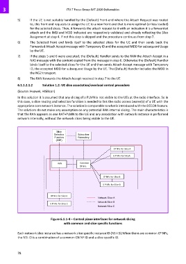
Figure 6.1.1-4 – Control plane interfaces for network slicing
with common and slice specific functions
Each network slice instance has a network slice specific instance ID (NSI-ID).When there are common CP NFs,
the NSI-ID is a combination of a common CN NF ID and a slice specific ID.
78