
Page 888 - 5G Basics - Core Network Aspects
P. 888
2 Transport aspects
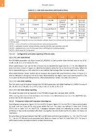
Table 12-1 – Link state transitions and transition times
To
L0 L2.1N L2.1B L2.2 L3
L0 NOOP < 1 second < 1 second N/A See clause
(Note 4) 11.2.2.12
L2.1N < 1 second NOOP < 1 second N/A See clause
(Note 4) 11.2.2.12
From L2.1B N/A < 1 second (Note 3) NOOP < 2 See clause
(Note 2) seconds 11.2.2.12
L2.2 (Note 2) N/A < 2 seconds < 2 seconds NOOP See clause
(Note 3) 11.2.2.12
L3 See clause 12.3 N/A N/A N/A NOOP
NOTE 1 – All times denote the maximum time between LinkState.request and LinkState.confirm primitives crossing the γ-O
reference point.
NOTE 2 – In the L2.1B and the L2.2 link states the link is always battery-powered.
NOTE 3 – Applicable only when running on battery powering and after mains powering is restored.
NOTE 4 – Applicable only in case of mains power failure and falling back to battery powering.
NOTE 5 – NOOP stands for "no operation".
12.1.1.7 Configuration and status reporting of the link state
12.1.1.7.1 Link state forced
The DPU-MIB parameter Link State Forced (LS_FORCED) is used to either force the link state to any of L0,
L2.1N, L2.1B, L2.2, or to release the link.
When AdminStatus="up" and the link is forced into an enabled link state (see 12.1.1.7.2), the allowed link
state transitions shown in Figure 12.1 shall be followed to bring the link to the forced link state. When the
link is requested to go to a link state that is not enabled, the forcing of the link state shall have no effect.
When AdminStatus="down" and the link is released, the allowed link state transitions shown in Figure 12.1
shall be followed to bring the link to the state determined by the higher layers and communicated to the
transceiver by the relevant DRA primitives. When AdminStatus="down", the link is forced to L3.
12.1.1.7.2 Link state enabling
The link states may be enabled through the DPU-MIB parameter Link State Enabling (LS_ENABLE) to any of
{L0, L3}, {L0, L3, L2.1N}, {L0, L3, L2.1N, L2.1B}, or {L0, L3, L2.1N, L2.1B, L2.2}.
12.1.1.7.3 Link state status reporting
The actual link state shall be reported in the DPU-MIB through the Link State (LINK_STATE).
NOTE – During a fast retrain or full initialization, the link state is L3 until both transceivers are in the SHOWTIME state,
at which time the link state becomes L0.
12.1.2 Transceiver states and transceiver state diagram
State diagrams are given in Figure 12-4 for the FTU-O and in Figure 12-5 for the FTU-R. States are indicated
by ovals, with the name of the state given within the oval. The states are defined in Table 12-4 for the
FTU-O and in Table 12-5 for the FTU-R. Transitions between states are indicated by arrows, with the
primitives or the events associated with them causing the transition listed next to the arrow. All states are
mandatory.
The primitives exchanged between the FME and ME (host controller) (preceded by "o:_" for the FTU-O and
"r:_", for the FTU-R) and events associated with them are shown in Table 12-2 and Table 12-3. The way in
which these events are implemented is vendor discretionary.
878