
Page 885 - 5G Basics - Core Network Aspects
P. 885
Transport aspects 2
The L0 state also facilitates power reduction by controlling the maximum transmission time during a TDD
frame. A PCE (see clause 5.1, which is beyond the scope of the ITU-T G.9701 transceiver), in cooperation
with the DRA and VCE, determines and updates from time to time the maximum allowed transmission time
for each line using corresponding control parameters at the γ reference point. This allows the ME to control
the actual power dissipation of a DP, keeping it under the desired limit.
The transmission time limit may vary from line to line and in some lines may reach the demarcation point
between US and DS. Discontinuous operation is efficiently used in this state to further reduce power
consumption.
No compromise on QoS is allowed in this state, except for the implied limit on the maximum bit rate due to
the reduced transmission time during TDD frame.
NOTE – Limit on the actual transmission time may be implemented by limiting the duration of the transmission
opportunities or by limiting the total number of symbols transmitted over all lines during a superframe, or both. The
configuration may be determined by the DRA/VCE.
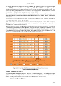
Figure 12-3 presents another example of downstream transmission during L0 state. During the presented
TDD frame MSF–1, the maximum number of symbol positions allowed for transmission is limited for all lines
and is less than the number of symbol positions available by the configured MF and Mds symbol values; lines
2, 3, 7 and 8 utilize the entire allowed transmission time, while other lines in the TDD frame MSF–1 use
discontinuous operation and thus only part of available symbol positions are used.
Figure 12-3 – Example of L0 link state operation with limited transmission
time in the downstream direction
12.1.1.4 Low power link state L2.1
This low power link state allows substantial reduction in power consumption at the expense of reduced
QoS (increased latency and significantly reduced maximum data rate). This state is primarily intended for
support of VoIP, while other services are unused, and is represented by two sub-states:
• L2.1 with mains powering (L2.1N);
875