
Page 664 - 5G Basics - Core Network Aspects
P. 664
2 Transport aspects
Annex X
Adaptation to the coax medium
(This annex forms an integral part of this Recommendation.)
X.1 Profile control parameters
Each profile specifies normative values for the following parameters:
− the number of subcarriers (N);
− the subcarrier spacing (fSC);
− the cyclic extension parameters LCP and β; and
− the maximum aggregate transmit power (applies to both downstream and upstream directions).
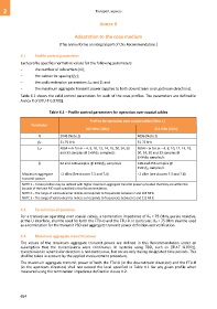
Table X.1 shows the valid control parameters for each of the coax profiles. The parameters are defined in
Annex X of [ITU-T G.9701].
Table X.1 – Profile control parameters for operation over coaxial cables
Profiles for operation over coaxial cables (Note 1)
Parameter
106 MHz (106c) 212 MHz (212c)
N 2048 (Note 2) 4096 (Note 3)
fSC 51.75 kHz 51.75 kHz
LCP N/64 × m for m = 4, 8, 10, 12, 14, 16, 20, 24, 30 N/64 × m for m = 4, 8, 10, 12, 14, 16,
and 33 samples @ 2×N×fSC samples/s 20, 24, 30 and 33 samples @
2×N×fSC samples/s
β 64 and 128 samples @ 2×N×fSC samples/s 128 and 256 samples @
2×N×fSC samples/s
Maximum aggregate +2 dBm (See clauses 7.3 and 7.4) +2 dBm (see clauses 7.3 and 7.4)
transmit power
NOTE 1 – Future profiles may be defined with higher maximum aggregate transmit powers provided that they are within the
bounds of the limit PSD mask specified in this Recommendation.
NOTE 2 – The range of valid subcarrier indices corresponds to frequencies between 2 and 106 MHz.
NOTE 3 – The range of valid subcarrier indices corresponds to frequencies between 2 and 212 MHz.
X.2 Termination impedance
For a transceiver operating over coaxial cables, a termination impedance of RV = 75 Ohm, purely resistive,
at the U interface, shall be used for both the FTU-O and the FTU-R. In particular, RV = 75 Ohm shall be used
as a termination for the transmit PSD and aggregate transmit power definition and verification.
X.3 Maximum aggregate transmit power
The values of the maximum aggregate transmit power are defined in this Recommendation under an
assumption that the transmissions were continuous. In systems using TDD, such as [ITU-T G.9701],
transmission in a particular direction is not continuous, but occurs only during designated time periods. This
shall be taken in account by the applied measurement procedure.
The maximum aggregate transmit power of both the FTU-O (in the downstream direction) and the FTU-R
(in the upstream direction) shall not exceed the level specified in Table X.1 for any given profile when
measured using the termination impedance defined in clause X.2.
654