
Page 661 - 5G Basics - Core Network Aspects
P. 661
Transport aspects 2
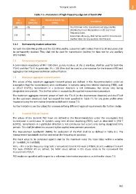
Table 7-5 – Parameters of high-frequency edge out-of-band LPM
ftr2 PSDtr2 Transition band, Δfth
Description
(MHz) (dBm/Hz) (MHz)
106 –76 20 The PSD limit in the transition band (Δfth) shall be
obtained by linear interpolation in dB over linear
frequency scale.
212 –79 40
Subcarriers above ftr2 shall not be used for transmission
(neither data nor any auxiliary information).
7.2.2 Permanently masked subcarriers
For both the 106 MHz profile and the 212 MHz profile, subcarriers with indices from 0 to 39 (inclusive) shall
be permanently masked. They shall not be used for transmission (neither for data nor for any auxiliary
information).
7.3 Termination impedance
A termination impedance of RV = 100 Ohm, purely resistive, at the U interface, shall be used for both the
FTU-O and the FTU-R. In particular, RV = 100 Ohm shall be used as a termination for the transmit PSD and
aggregate transmit power definition and verification.
7.4 Maximum aggregate transmit power
The values of the maximum aggregate transmit power are defined in this Recommendation under an
assumption that the transmissions were continuous. In systems using time-division duplexing (TDD), such
as [ITU-T G.9701], transmission in a particular direction is not continuous, but occurs only during
designated time periods. This shall be taken in account by the applied measurement procedure.
The maximum aggregate transmit power of both the FTU-O (in the downstream direction) and the FTU-R
(in the upstream direction) shall not exceed the level specified in Table 7-1 for any given profile when
measured using the termination impedance defined in clause 7.3.
Further limitations are the subject for annexes defining different regional requirements (for further study).
8 Transmit PSD verification
The values of the transmit PSD mask are defined in this Recommendation under the assumption that
transmission is continuous. In systems using time division duplexing (TDD), such as described in [ITU-T
G.9701], transmission in a particular direction is not continuous but occurs only during designated time
periods. This shall be taken into account by the applied measurement procedure.
The measurement bandwidth (MBW) for evaluation of the PSD shall be as defined in Table 8-1. The
measurement bandwidth shall be centred on the frequency in question.
The mask value to be compared against shall be the maximum value the mask takes within a window
[f − ½×MBW, f + ½×MBW].
NOTE – If in a certain frequency range both a narrowband transmit PSD mask (TXPSDM_N) and a wideband transmit
PSD mask (TXPSDM_W) are defined, the MBW values defined in this clause relate to the narrowband PSD
measurements PSD_N.
PSD masks are specified with respect to a reference termination impedance, as defined in clause 7.3.
651