
Page 628 - 5G Basics - Core Network Aspects
P. 628
2 Transport aspects
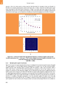
penalty in this 5 km MFH system. At the required EVM threshold for 64-QAM of 8% (see [b-3GPP TS
36.104]), the received optical power needs to be larger than −21 dBm. Given the fact that optical signal
power generated by the DML-based transmitter is 8 dBm, the optical path loss budget is thus 29 dB,
meeting the N1 and N2 loss budget requirements for PONs. We expect that with additional performance
improvement techniques, such as optical pre-amplification, the link loss budget can be further increased.
a)
b)
Figure 9-21 – a) The mean EVM of the aggregated LTE signals as a function of optical path loss and
received optical power for L = 0 km and L = 5 km; and b) a typical recovered 64-QAM constellation of one
of the 48 LTE signals after 5 km SSMF transmission
with PRX = −6 dBm
9.2.4 Multiple uplink signals transmission
Figure 9-22 shows the typical experimental set-up to investigate the transmission performances of typical
LTE uplink signals in a normal MIMO antenna configuration. It consists of an LTE VSG, electrical splitter,
MIMO antennas, LNAs, frequency-down-converters, BPFs, RF combiner, a VEA, a RoF transmitter, SMF, a
VOA, a RoF receiver, and an LTE VSA. EDFA and OBPF are employed in front of RoF receiver as a pre-
amplifier to improve the total link power budget. The LTE VSG generated two adjacent uplink LTE channels
with the radio carrier frequency of 2.540 and 2.560 GHz to support multi-frequency assignment (FA). The 2
LTE uplink signals generated were employed as incoming signals for the MIMO antennas (Ant-1 and Ant-2).
The bandwidth of each uplink signal was 20 MHz, in which the LTE band #7 was assumed (see [b-3GPP TS
36.101]). To emulate a free-space propagation loss, the generated uplink LTE signals were manually
attenuated by 50 to 90 dB with the VEA. To configure a desired IF-band RoF transmission scheme, the LTE
uplink signals from each antenna were frequency-down converted and bandpass filtered to be suitable for
618