
Page 508 - 5G Basics - Core Network Aspects
P. 508
1 Core network aspects
Appendix I
Architecture reference model
(This appendix does not form an integral part of this Recommendation)
The architecture reference models are explained considering both the non-roaming case and the roaming
case. The aggregated reference points, m1 through to m4 are used to explain the relationship among UE, A-
MMCF and C-MMCF in home and visited networks. m1 is the interface between A-MMCF and C-MMCF, m2
is the interface between UE and A-MMCF, m3 is the interface between UE and C-MMCF, and m4 is the
interface between the two C-MMCF in home and visited networks. The MMCF is composed of several
functional entities and the detailed reference points between those functional entities and the other
functional entities in NGN are defined in clause 6.5.
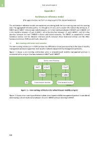
I.1 Non-roaming architecture and scenarios
The non-roaming architecture in NGN can have two different architectures according to the type of mobility
management protocols supported, host-based or network-based mobility management protocols.
Figure I.1 shows a non-roaming architecture when a network-based mobility management protocol is
considered while using an interface between A-MMCF and C-MMCF.
Service control functions
NACF A-RACF C-RACF
A-MMCF C-MMCF
m1
UE Access transport functions Core transport functions
Y.2018(09)_FI.1
Figure I.1 – Non-roaming architecture for network-based mobility using m1
Figure I.2 shows a non-roaming architecture when a host-based mobility management protocol is considered
while having a direct relationship between UE and C-MMCF without involving A-MMCF.
498