
Page 1109 - 5G Basics - Core Network Aspects
P. 1109
Transport aspects 2
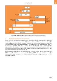
Figure 6-8 – SOTUm interface principal information containment relationships
7 Multiplexing/mapping principles and bit rates
Figure 7-1 shows the relationship between various information structure elements and illustrates the
multiplexing structure and mappings for the OTU. In the multi-domain OTN any combination of the ODU
multiplexing layers may be present at a given OTN NNI. The interconnection of and visibility of ODU
multiplexing layers within an equipment or domain is outside the scope of this Recommendation. Figure 7-
1 shows that a (non-OTN) client signal is mapped into an OPU. This OPU signal is mapped into the
associated ODU. This ODU signal is either mapped into the associated OTU[V] signal, or into an ODTU. This
ODTU signal is multiplexed into an ODTU Group (ODTUG). The ODTUG signal is mapped into an OPU. This
OPU signal is mapped into the associated ODU, etc.
The OPUk (k=0,1,2,2e,3,4,flex) are the same information structures, but with different client signals. The
OPUCn has a different information structure than the OPUk; the OPUCn information structure consists of n
times the information structure of the OPU while the OPUk contain a single instance of the OPU
information structure.
1099