
Page 1081 - 5G Basics - Core Network Aspects
P. 1081
Transport aspects 2
VI.2 Examples of discontinuous operation with vectoring enabled
If vectoring is enabled, different bit loading tables and different sets of gains may be defined for NOI and
DOI. The settings of TTR, TBUDGET, TA and TIQ are determined by the DRA/VCE based on the data traffic as
defined in clause 10.7. The value of TIQ is set by the DRA/VCE and communicated to the FTU-O's in the
vectored group. The values of B' and B are derived and dependent on the sync symbol presence (or non-
presence) in the logical and its position in the logical frame.
Figure 10-29 (for the downstream direction) and Figure 10-30 (for the upstream direction) show examples
of coordinated discontinuous operation where the vector processing (i.e., vectored group matrix size) is
reduced in the DOI, thereby achieving some power savings with fewer operations in matrix multiplications.
For each line the DRA/VCE has set TIQ=1 indicating to the FTU-O to insert an idle symbol if there is no data
available for the remaining intervals in TBUDGET allocated for data in the DOI.
The symbol periods in the DOI across all the lines of the vectored group should be configured in a manner
that achieves a good balance between performance and power savings. Transceiver power saving may be
achieved through the use of quiet symbols when no data is present and in the alignment of data symbols
among selected lines in the vector group to reduce the cancellation matrix size.
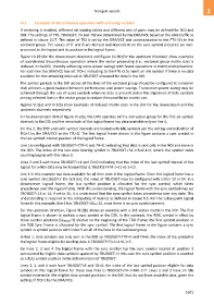
Figures VI.2(a) and VI.2(b) show examples of reduced matrix sizes in the DOI for the downstream and the
upstream channels respectively.
In the downstream DOI of Figure VI.2(a), the DPU operates with a 3x3 vector group for the first six symbol
intervals in the DOI and the remainder of the logical frame has data available only on line 4.
On line 2, the fifth and sixth symbol intervals are loaded with idle symbols per the setting and indication of
TIQ=1 by the DRA/VCE to the FTU-O. The first logical frame shown in this figure contains a sync symbol in
the last symbol interval position of the logical frame.
Line 1 is configured with TBUDGET=TTR=5 and TA=0, indicating that data is sent only in the NOI and none in
the DOI. The index of the last data bearing symbol is TBUDGET+TA-1=5+0-1=4, where the symbol index
counting begins with the value 0.
Lines 2 and 3 each have TBUDGET=11 and TA=0 indicating that the index of the last symbol interval of the
logical for which data may be transmitted is TBUDGET+TA-1=11+0-1=10.
Line 4 in this example has data available for all time slots in the logical frame. Since this logical frame has a
sync symbol allocated for the last slot, the value of TBUDGET may be configured with either 13 or 14. In a
downstream logical frame, the last symbol position is allocated for the sync symbol, which takes
precedence over the logical frame. With this understanding, the logical frame with the sync symbol may set
TBUDGET=13 or 14; if set to 14, it is understood that the sync symbol takes precedence over any data. This
understanding is required in the computing of NB(k+1) as defined in clause 9.5. For the subsequent logical
frame in this example, line 4 has TBUDGET=Mds=14, since there is no sync symbol present.
For the upstream direction, Figure VI.2(b) shows an example with a 3x3 vector matrix in the DOI. The first
logical frame is shown to contain a sync symbol in the DOI. In this example, the RMC symbol is offset by
three symbol positions (DRMCus=3) relative to the beginning of the TDD frame; the first symbol position in
the TDD Sync Frame is allocated for the sync symbol. The first logical frame in the figure contains a sync
symbol in symbol position with index 5 on all of the lines in the vectored group.
In line 1, data symbols are only sent in the NOI so TBUDGET=TTR=4 and TA=0; the index of the symbol in
the logical frame eligible for sending data is TBUDGET+TA-1=4+0-1=3.
On lines 2, 3 and 4 the logical frame with the sync symbol has the sync symbol located in position 5
surrounded by eligible data symbols spanned by TBUDGET; in this case the sync symbol position is counted
as a data symbol position in the determination of TBUDGET.
Lines 2, 3, and 4 each have TBUDGET=8 and TA=0; the index of the last symbol position eligible for data
symbols in this logical frame for these two lines is TBUDGET+TA-1=8+0-1=7. Lines 2 and 3 have an idle
symbol inserted in the eligible data symbol positions in the DOI that do not have available data, given the
setting of TIQ=1 by the DRA/VCE.
1071