Page 281 - Kaleidoscope Academic Conference Proceedings 2024
P. 281

Innovation and Digital Transformation for a Sustainable World


                                     L
                          h h  +
                                         x +
                     y =  ( rl H  sr  h sl H )   i i    , i  (3)   10   RIS-NOMA
                      l
                                     i l =                                AF-Relay NOMA
           The signal to interference plus noise ratio of the vehicle        8
           after decoding the signal     can be written as        6
                                  
                                h h  H    h  +  2            Maximum Achievable Rate (Mbps/Hz)
                     SINR =      rl  sr  l  sl  l        (4)
                         l   L                2                   4
                               ( rl H  sr  h sl H ) +  i  +   2
                                h h 
                            i l =  +  1                           2
           The achievable rate can be calculated using the Shannon’s
           theorem [17] and can be given by                       0
                                                                   0      5     10     15     20     25    30
                         =  log 2 (1 SINR l )                                        SNR(dB)
                                +

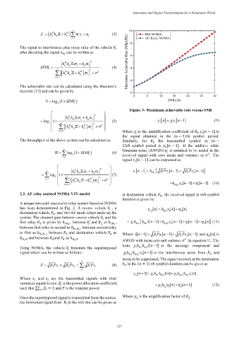
                                                                  Figure 3- Maximum achievable rate versus SNR
                                                    
                                 h h  H    h  +  2  
                     =  log 1   2  rl  sr  l  sl  l   +  (5)                 x 1   n =   1 1  r n −   1  (9)
                              L   H       H   2    2 
                                  h h 
                               ( rl  sr  h sl  ) +  i  +   
                             i l =  +  1                    Where    is the amplification coefficient of    ,   [   − 1] is
                                                                     1
                                                                                                   1 1
                                                              the  signal  obtained  in  the  (   − 1)  ℎ  symbol  period.
           The throughput of the above system can be calculated as   Similarly,  for     2   the  transmitted  symbol  in  (   −
                                                              1)  ℎ  symbol  period  is     [   − 1] .  If  the  additive  white
                                                                                   2
                                 L
                                        +
                             =  log 2 (1 SINR l )      (6)   Gaussian noise (AWGN)     is assumed to be added in the
                                                                                    1
                                                              received  signal  with  zero  mean  and  variance  as    .  The
                                                                                                         2
                                l= 1
                                                              signal    [   − 1] can be expressed as
                                                                    1
                                    H            2                                                 
                                                                                        1]
                        L
                      =   log 1   2  L  h h  rl  sr    l  h  +  sl  l   +  (7)   r 1 n −   1 =  h sR 1    1 Ps 1 [n − +    2 Ps 2 [n − 1]
                                      H
                        l= 1       h h    h H  ) +  2  +   2 
                                   ( rl  sr  sl  i     
                                                                                               1] 
                                i l =  +  1                                         + h R 1 2 R  x 2 [n− +  1 [n− 1]  (10)
           2.2. AF relay assisted NOMA V2V model              at destination vehicle    , the received signal in     ℎ symbol
                                                                                   
                                                              duration is given by
           A unique two-path successive relay system based on NOMA
           has  been  demonstrated  in  Fig.  2.  A  source  vehicle     ,  a  y  [ ] n =  h x  [ ] n  [ ] n
                                                                                        +
                                                         
           destination vehicle    , and two AF mode relays make up the      d V    1 R d  1  d
                             
           system. The channel gain between source vehicle     and the
                                                      
                                                                                                  1] 
                                                                                          1] 
                                                                        h
                                                                               1] h
           first  relay     is  given  by ℎ      1 ,  between     and     as ℎ      2 ,  =   1 h  1 R d   sR 1  [ x n − +  R 2 1 R  x 2 [n − +  1 [n − +  d [n   ] (11)
                                               
                     1
                                                   2
           between first relay to second as ℎ  , between second relay
                                         1    2
           to first as ℎ  , between     and destination vehicle     as
                                                                        1]
                                                                                     1]
                        2    1    1                           Where  [ x n − =    1 Ps 1 [n − +    2 Ps 2 [n − 1] and    [  ] is
                                                                                                           
           ℎ    1     and between    and     as ℎ    2    .   AWGN with mean zero and variance    . In equation 11, The
                                  
                           2
                                                                                             2
                                                              term   h h  [ x n− 1] is  the  message  component  and
           Using  NOMA,  the  vehicle     transmits  the  superimposed  1 sR 1 R d
                                                                         1
                                     
           signal which can be written as follows:             1 h h  2 1 x 2 [n − 1] is  the  interference  noise  from    and
                                                                                                          2
                                                                  1 R d R R
                                                              needs to be suppressed. The signal received at the destination
                                         2
                                      2 
                     S =   Ps +   Ps =     Ps         (8)       in the (   + 1)   ℎ symbol duration can be given as
                                                                 
                           1  1    2          i  i
                                         i= 1
                                                                         1] 
                                                                   y  d V  [n+ =  2 sR  2 R d  [ ] n +   2 R 1 2 R  h x 1 [ ] n
                                                                              h h x
                                                                                         h
                                                                                              2 R d
           Where      and      are  the  transmitted  signals  with  their      1
                         2
                  1
           variances equals to one.     is the power allocation coefficient,  +  h  [ ] n  [n+ 1]       (12)
                                                                                        +
                                 
           such that ∑ 2   =1    = 1 and    is the transmit power.               2  2 R  2  d
                          
           Once the superimposed signal is transmitted from the source,   Where     is the amplification factor of    .
                                                                                               2
                                                                     2
           the forwarded signal from     in the     ℎ slot can be given as
                                  1
                                                          – 237 –
   276   277   278   279   280   281   282   283   284   285   286