
Page 1443 - 5G Basics - Core Network Aspects
P. 1443
Signalling aspects 3
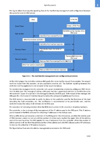
The figure below illustrates the signalling flow of the membership management and configuration between
the controller and the BNG device.
BNG Controller
Initial Phase Create a BNG Pool
Add BNG as the member of the
BNG pool
Add member
Add BNG Pool member(Pool ID)
BNG Pool function activation
Add BNG Pool member response
Running Phase Periodically report the status of
BNG
Remove BNG from the
BNG pool
Remove member
Remove BNG Pool member(Pool ID, BNG id)
BNG Pool function deactivation
Remove BNG Pool member response
Figure 8-1 – The membership management and configuration procedure
At the initial phase, the controller creates a BNG pool after receiving the request from outside. The request
could be issued from the operator, or one application module, etc. The detailed signalling between the
controller and the application is not included in this recommendation.
For membership management, the controller sets up one membership relation by adding one BNG device
into the BNG pool. The message of adding a BNG pool member is generated and sent to the BNG device by
the controller. A pool ID is carried in this message to identify the BNG pool. With receipt of the message, the
BNG gets the information of membership and enables the corresponding BNG pool functions.
The BNG device is recommended to notify its status to the controller used for the functions of the load
balancing, the fault protection, etc. This notification is recommended to be periodically sent, and the
controller knows the status of all members in the BNG pool.
The procedure of removing members from the BNG pool is similar to the procedure of adding members.
The controller is also in charge of the management of the IP address pool in the BNG pool. This IP address
pool is located in the BNG, and used for allocating IP addresses to the dial-up users.
When a BNG device just becomes a member of the BNG pool at the initial phase, or when the address pool
of BNG devices is about to run out and the number of online users reaches the upper limit of the address
pool at the running phase, the BNG applies for new IP addresses from the controller. When the number of
online users is much less than the address number of the address pool, the BNG releases parts of IP addresses
to improve the utilization of IP address resource.
The figure below illustrates the address management procedure in the BNG pool.
1433