Page 1231 - 5G Basics - Core Network Aspects
P. 1231

Transport aspects                                              2


            A group of 'M' successive extended ODUj bytes is de-mapped from a group of 'M' successive ODTUk.M
            bytes.
            NOTE 2 – For the case where the ODUj signal is output as an OTUj signal, frame alignment of the extracted extended
            ODUj signal is to be recovered to allow frame synchronous mapping of the ODUj into the OTUj signal.
            During  a  signal  fail  condition  of  the  incoming  ODUk/OPUk  signal  (e.g.,  in  the  case  of  an  ODUk-AIS,
            ODUk-LCK,  ODUk-OCI  condition)  the  ODUj-AIS  pattern  as  specified  in  clause  16.5.1  is  generated  as  a
            replacement signal for the lost ODUj signal.

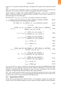
            The values of M, m, Cm,min, Cm,max, n, Cn,min and Cn,max for ODUj into ODTUk.ts are as follows:
                      ODUj _ nom  _bit  _ rate  1(  ODUj _bit  _ rate _tolerance   00006.0   )   for ODUj with j ≠ flex(GFP)   (19-1a)
             M   ceiling                                            
                      (ODTUk  1 .  _ nom _bit  _ rate  1(  ODTUk .ts _bit  _ rate _tolerance )  
                            M  ODUk_    bit _ rate/ ODUk. ts _ bit _ rate  for ODUj with j = flex(GFP)   (19-1b)

                                                       m  8  M                                       (19-2)
                              ODUj_  nom_  bit _ rate  Number _ of _ GMP_ blocks _ in _ ODTUk. ts  
                     c m, nom                                                                         (19-3)
                             
                                                ODTUk _1.  nom_  bit _ rate M                    
                                                   1  ODUj_   bit _ rate _ tolerance  
                                   c m min,   c m, nom                                           (19-4)
                                                   1  ODTUk _1.  bit _ rate _ tolerance  
                                                   1  ODUj_   bit _ rate _ tolerance  
                                  c m max,   c m, nom                                             (19-5)
                                                  
                                                   1  ODTUk _1.  bit _ rate _ tolerance  
                                                  C        floor c                                  (19-6)
                                                    m , min       m , min
                                                  C       ceiling c                                 (19-7)
                                                   m , max         m , min
                                                          n      8                                    (19-8)
                              ODUj_  nom _ bit _ rate  Number _ of _ GMP_ blocks _ in _ ODTUk. ts 
                     c n, nom                                                                        (19-9)

                                                  ODTUk _1.  nom_   bit _  rate                   
                                                  1   ODUj_  bit _ rate _ tolerance  
                                   c n min,   c n, nom                                          (19-10)
                                                  1  ODTUk _1.  bit _ rate _ tolerance  
                                                  1  ODUj_   bit _ rate _ tolerance  
                                   c n max,   c n, nom                                           (19-11)
                                                 
                                                  1 ODTUk _1.  bit _  rate _ tolerance  
                                                   C       floor c                                 (19-12)
                                                     , n  min      , n  min
                                                  C      ceiling c                                 (19-13)
                                                    , n  max       , n  min
            Cm,min, Cn,min (n=8), Cm,max and Cn,max (n=8) values represent the boundaries of ODUj/ODTUk.M ppm offset
            combinations  (i.e., min.  ODUj/max.  ODTUk.M  and  max.  ODUj/min.  ODTUk.M).  In  steady  state,  given
            instances  of  ODUk/ODTUk.M  offset  combinations  should  not  result  in  generated  Cn  and  Cm  values
            throughout this range but rather should be within as small a range as possible.
            NOTE – Under transient ppm offset conditions (e.g., AIS to normal signal), it is possible that Cn and Cm values outside
            the range Cn,min to Cn,max and Cm,min to Cm,max may be generated and a GMP de-mapper should be tolerant of such
            occurrences. Refer to Annex D for a general description of the GMP principles.
            19.6.1  Mapping ODUj into ODTU2.M

            Groups  of  M  successive  bytes  of  the  extended  ODUj  (j  =  0,  flex)  signal  are  mapped  into  a  group  of  M
            successive bytes of the ODTU2.M payload area under control of the GMP data/stuff control mechanism.


                                                                                                        1221
   1226   1227   1228   1229   1230   1231   1232   1233   1234   1235   1236