
Page 1224 - 5G Basics - Core Network Aspects
P. 1224
2 Transport aspects
For the case where the ODUj is received from the output of a fabric (ODU connection function), the
incoming signal may contain (in the case of an open matrix connection), the ODUj-OCI signal as specified
in clause 16.5.2. This ODUj-OCI signal is then mapped into the ODTUjk.
NOTE 2 – Not all equipment will have a real connection function (i.e., switch fabric) implemented; instead, the
presence/absence of tributary interface port units represents the presence/absence of a matrix connection. If such a
unit is intentionally absent (i.e., not installed), the associated ODTUjk signals should carry an ODUj-OCI signal. If such a
unit is installed but temporarily removed as part of a repair action, the associated ODTUjk signal should carry an ODUj-
AIS signal.
The de-mapping of ODUj signals from the ODTUjk signal (j = 0,1,2; k = 1,2,3) is performed by extracting the
extended ODUj signal from the OPUk under control of its justification overhead (JC, NJO, PJO1, PJO2).
NOTE 3 – For the case where the ODUj signal is output as an OTUj signal, frame alignment of the extracted extended
ODUj signal is to be recovered to allow frame synchronous mapping of the ODUj into the OTUj signal.
During a signal fail condition of the incoming ODUk/OPUk signal (e.g., in the case of an ODUk-AIS, ODUk-
LCK, ODUk-OCI condition) the ODUj-AIS pattern as specified in clause 16.5.1 is generated as a replacement
signal for the lost ODUj signal.
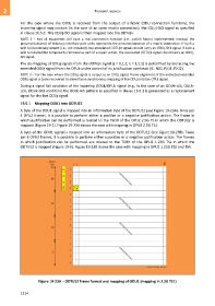
19.5.1 Mapping ODU1 into ODTU12
A byte of the ODU1 signal is mapped into an information byte of the ODTU12 (see Figure 19-23A). Once per
4 OPU2 frames, it is possible to perform either a positive or a negative justification action. The frame in
which justification can be performed is related to the TSOH of the OPU2 2.5G TS in which the ODTU12 is
mapped (Figure 19-1). Figure 19-23A shows the case with mapping in OPU2 2.5G TS1.
A byte of the ODU1 signal is mapped into an information byte of the ODTU12 (see Figure 19-23B). Twice
per 8 OPU2 frames, it is possible to perform either a positive or a negative justification action. The frames
in which justification can be performed are related to the TSOH of the OPU2 1.25G TSs in which the
ODTU12 is mapped (Figure 19-1). Figure 19-23B shows the case with mapping in OPU2 1.25G TS2 and TS4.
Figure 19-23A – ODTU12 frame format and mapping of ODU1 (mapping in 2.5G TS1)
1214