
Page 1218 - 5G Basics - Core Network Aspects
P. 1218
2 Transport aspects
1 2 3 4 5 6 7 8
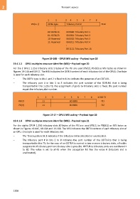
PSI[1+ i] ODTU type Tributary Port # TS #i
00: ODTU13 00 0000: Tributary Port 1
01: ODTU23 00 0001: Tributary Port 2
10: Reserved 00 0010: Tributary Port 3
11: Reserved 00 0011: Tributary Port 4
:
00 1111: Tributary Port 16
Figure 19-16B – OPU3 MSI coding – Payload type 20
19.4.1.3 OPU1 multiplex structure identifier (MSI) – Payload type 20
For the 2 OPU1 1.25G tributary slots 2 bytes of the PSI are used (PSI[2], PSI[3]) as MSI bytes as shown in
Figures 19-14A and 19-17. The MSI indicates the ODTU content of each tributary slot of the OPU1. One byte
is used for each tributary slot.
– The ODTU type in bits 1 and 2 is fixed to 11 to indicate the presence of an ODTU01.
– The tributary port # in bits 3 to 8 indicates the port number of the ODTU01 that is being
transported in this 1.25G TS; the assignment of ports to tributary slots is fixed, the port number
equals the tributary slot number.
1 2 3 4 5 6 7 8 1.25G TS
PSI[2] 11 00 0000 TS1
PSI[3] 11 00 0001 TS2
Figure 19-17 – OPU1 MSI coding – Payload type 20
19.4.1.4 OPU4 multiplex structure identifier (MSI) – Payload type 21
For the eighty OPU4 1.25G tributary slots 80 bytes of the PSI are used (PSI[2] to PSI[81]) as MSI bytes as
shown in Figures 19-14C, 19-18A and 19-18B. The MSI indicates the ODTU content of each tributary slot of
an OPU. One byte is used for each tributary slot.
– The TS occupation bit 1 indicates if the tributary slot is allocated or unallocated.
– The tributary port # in bits 2 to 8 indicates the port number of the ODTU4.ts that is being
transported in this TS; for the case of an ODTU4.ts carried in two or more tributary slots, a flexible
assignment of tributary port to tributary slots is possible. ODTU4.ts tributary ports are numbered 1
to 80. The value is set to all-0s when the occupation bit has the value 0 (tributary slot is
unallocated).
1208