
Page 1209 - 5G Basics - Core Network Aspects
P. 1209
Transport aspects 2
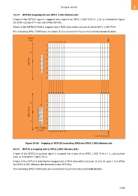
19.3.4 ODTU01 mapping into one OPU1 1.25G tributary slot
A byte of the ODTU01 signal is mapped into a byte of an OPU1 1.25G TS #i (i = 1,2), as indicated in Figure
19-10 for a group of 4 rows out of the ODTU01.
A byte of the ODTU01 TSOH is mapped into a TSOH byte within column 16 of the OPU1 1.25G TS #i.
The remaining OPU1 TSOH bytes in column 15 are reserved for future international standardization.
MFAS
bit 8 1904
1 2 3 4 5 6 7 8
1
2
0
3
JC 4
ODTU01 JC 1
JC
2
1 NJO
3
4
1
2
0
3
OPU1 TS #i RES RES JC JC 4 1
RES JC 2
1
NJO 3
OPU1 TSOH 4
of TS #i
1904
1 2 3 4 5 6 7 8
G.709-Y.1331(12)_F9-10
Figure 19-10 – Mapping of ODTU01 (excluding JOH) into OPU1 1.25G tributary slot
19.3.5 ODTU2.ts mapping into ts OPU2 1.25G tributary slots
A byte of the ODTU2.ts payload signal is mapped into a byte of an OPU2 1.25G TS #i (i = 1,..,ts) payload
area, as indicated in Figure 19-11.
A byte of the ODTU2.ts overhead is mapped into a TSOH byte within columns 15 and 16, rows 1 to 3 of the
last OPU2 1.25G tributary slot allocated to the ODTU2.ts.
The remaining OPU2 TSOH bytes are reserved for future international standardization.
1199