
Page 1198 - 5G Basics - Core Network Aspects
P. 1198
2 Transport aspects
MFAS Multi- Column
bits frame Frame
(6)78 row row 1 ..... 15 16 17 18 19 20 21 22 23 24 25 26 ..... 3823 3824
1 1
2 2
(0)00 TSOH TS1 .....
3 3
4 4
5 1
6 2
(0)01 TSOH TS2 .....
7 3
8 4
.....
13 1
14 2
(0)11 TSOH TS4 .....
15 3
16 4
17 1 1
18 2 2
(1)00 TSOH TS1 or TS5 .....
19 3 3
20 4 4
..... .....
29 13 1
30 14 2
(1)11 TSOH TS4 or TS8 .....
31 15 3 1 2 3 4 5 6 7 8 1 2 7 8 1.25G TS#
32 16 4 1 2 3 4 1 2 3 4 1 2 3 4 2.5G TS#
G.709-Y.1331(12)_F19-1
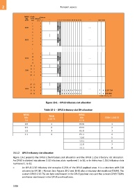
Figure 19-1 – OPU2 tributary slot allocation
Table 19-1 – OPU2 tributary slot OH allocation
MFAS MFAS
TSOH
bits bits TSOH 1.25G TS
2.5G TS
7 8 6 7 8
0 0 1 0 0 0 1
0 1 2 0 0 1 2
1 0 3 0 1 0 3
1 1 4 0 1 1 4
1 0 0 5
1 0 1 6
1 1 0 7
1 1 1 8
19.1.2 OPU3 tributary slot allocation
Figure 19-2 presents the OPU3 2.5G tributary slot allocation and the OPU3 1.25G tributary slot allocation.
An OPU3 is divided into sixteen 2.5G tributary slots numbered 1 to 16, or in thirty-two 1.25G tributary slots
numbered 1 to 32.
– An OPU3 2.5G tributary slot occupies 6.25% of the OPU3 payload area. It is a structure with 238
columns by 64 (16 4) rows (see Figures 19-2 and 19-8) plus a tributary slot overhead (TSOH). The
sixteen OPU3 2.5G TSs are byte interleaved in the OPU3 payload area and the sixteen OPU3 TSOHs
are frame interleaved in the OPU3 overhead area.
1188