
Page 89 - ITU Kaleidoscope 2016
P. 89
ICTs for a Sustainable World
fibre in terms of cut-off wavelength, mode-field diameter
(MFD), zero-dispersion wavelength and bending loss
characteristics. These requirements result in an example
refractive index of 2a = 8.0 µm, ∆ = 0.35%, a1/a = 2.5 and
wt/2a = 0.5. Here, a and ∆ values are mainly determined by
the MFD, zero-dispersion wavelength, and bending loss
requirements. Roughly speaking, a1/a, wt/2a and ∆t values
are relating with the cut-off wavelength and crosstalk (XT)
requirements.
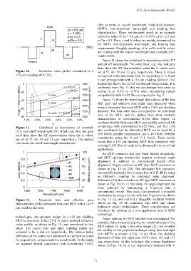
Figure 11 shows the calculated ∆t dependence of the XT
and cut-off wavelength. The solid black, red, blue and grey
lines show the XT characteristics when the Λ values were
Figure 10. Refractive index profile considered in a set at 57, 46, 39 and 33 µm, respectively. These Λ values
125 µm cladding MCF [19]. correspond to the maximum limit for supporting 2, 3, 4 and
5 core arrangements with a 125 µm cladding diameter. The
dashed line shows the cut-off wavelength characteristic. It is
confirmed from Fig. 11 that we can arrange four cores by
setting ∆t at -0.5% to -0.74% while maintaining optical
compatibility with G.652 fibre as expected in Fig. 7.
Figure 12 shows the wavelength dependence of the loss
(left axis) and effective area (right axis) measured when
using a fabricated four-core MCF with a 124.9 µm cladding
diameter. The four solid lines correspond to the individual
core in the MCF, and the dashed lines show example
characteristics of conventional G.652 fibre. Figure 12
confirms that the fabricated MCF successfully achieved full
Figure 11. Calculated ∆t dependence of crosstalk compliance with conventional G.652 fibre, and Ref. [19]
(XT) and cutoff wavelength [19]. Black, red, blue and gray also confirmed that the fabricated MCF can be used for a
solid lines show the XT characteristics when the Λ values 100 Gbit/s parallel transmission and a 40 Gbit/s DWDM
are set at 57, 46, 39 and 33 µm, respectively. The dashed transmission using the O and C+L bands. These results
line shows the cutoff wavelength characteristic. reveal that a 125 µm cladding MCF fully compliant with
existing G.652 fibre is ready to be discussed in terms of real
applications.
An MCF connector has also been studied intensively,
and MCF splicing intrinsically requires rotational angle
alignment in addition to conventional lateral offset
alignment. Nagase realized an MU type MCF connector as
shown in Fig. 13 (a) [20]. The fabricated MU connector
successfully realized a low average loss of 0.13 dB by using
an Oldham’s coupling for rotational angle alignment.
Reference [21] also describes an SC type MCF connector as
shown in Fig. 13 (b). In this study, the angle alignment has
been achieved by introducing a V-groove into a
conventional ferrule. This study also proposed a rotatable
mechanism by using a ferrule with four V-grooves as shown
Figure 12. Measured loss and effective area in Fig. 13 (c), and realized a pluggable add/drop module
characteristics of the fabricated four-core MCF with a 124.9 shown as Fig. 13 (d) combined with MCF and planar
µm cladding diameter. lightwave circuit technologies. These considerations are
beneficial for opening up a new application area of SDM
technology.
technologies. An optimum design for a 125 µm cladding Fusion splicing for MCF has also been investigated. For
MCF is described in Ref. [19]. A trench assisted refractive example, Saito proposed aligning the rotational angle of the
index profile, as shown in Fig. 10, was considered in this MCF simply by using a side-view image [22]. He revealed
study. The centre core and inner cladding radius are the validity of the proposed technique using four and eight
assumed to be a and a1, respectively. The relative index core MCFs as shown in Fig. 14 (a). Here, the cladding
difference of the centre core and trench are defined as ∆ and diameters of four and eight core MCFs were 125 and 175
∆t, respectively. wt represents the trench width. In this study, µm, respectively. In this technique, the average brightness
we assumed optical consistency with conventional G.652
shown in Figs. 14 (b) or (c), respectively obtained with 4-
– 71 –