
Page 39 - ITU Journal Future and evolving technologies – Volume 2 (2021), Issue 2
P. 39
ITU Journal on Future and Evolving Technologies, Volume 2 (2021), Issue 2
delivery procedures, namely ABD2D and DBD2D are pre‑ vice versa. For this purpose, time is divided into segments
sented. For both, it is assumed that clustering and cache and each segment includes a varying number of time slots
placement operations are applied beforehand. where a time slot is the smallest piece of time. All of the
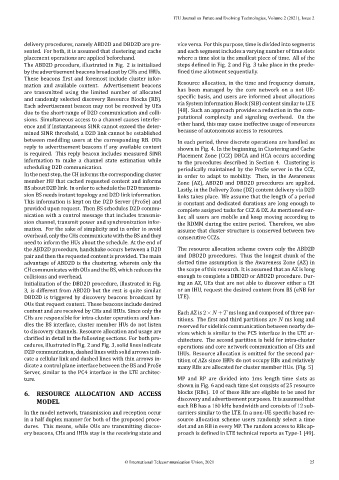
The ABD2D procedure, illustrated in Fig. 2 is initialized steps de ined in Fig. 2 and Fig. 3 take place in the prede‑
by the advertisement beacons broadcast by CHs and IHUs. ined time allotment sequentially.
These beacons irst and foremost include cluster infor‑
mation and available content. Advertisement beacons Resource allocation, in the time and frequency domain,
are transmitted using the limited number of allocated has been managed by the core network on a not UE‑
and randomly selected discovery Resource Blocks (RB). speci ic basis, and users are informed about allocations
Each advertisement beacon may not be received by UEs via System Information Block (SIB) content similar to LTE
due to the short‑range of D2D communication and colli‑ [48]. Such an approach provides a reduction in the com‑
sions. Simultaneous access to a channel causes interfer‑ putational complexity and signaling overhead. On the
ence and if instantaneous SINR cannot exceed the deter‑ other hand, this may cause ineffective usage of resources
mined SINR threshold, a D2D link cannot be established because of autonomous access to resources.
between meddling users at the corresponding RB. OUs In each period, three discrete operations are handled as
reply to advertisement beacons if any available content shown in Fig. 4. In the beginning, in Clustering and Cache
is required. This reply beacon includes measured SINR Placement Zone (CCZ) DBCA and HCA occurs according
information to make a channel state estimation while to the procedures described in Section 4. Clustering is
scheduling D2D communication. periodically maintained by the ProSe server in the CCZ,
In the next step, the CH informs the corresponding cluster in order to adapt to mobility. Then, in the Awareness
member HU that cached requested content and informs Zone (AZ), ABD2D and DBD2D procedures are applied.
BS about D2D link. In order to schedule the D2D transmis‑ Lastly, in the Delivery Zone (DZ) content delivery via D2D
sion BS needs instant topology and D2D link information. links takes place. We assume that the length of a period
This information is kept on the D2D Server (ProSe) and is constant and dedicated durations are long enough to
provided upon request. Then BS schedules D2D commu‑ complete assigned tasks for CCZ & DZ. As mentioned ear‑
nication with a control message that includes transmis‑ lier, all users are mobile and keep moving according to
sion channel, transmit power and synchronization infor‑ the RDMM during the entire period. Therefore, we also
mation. For the sake of simplicity and in order to avoid assume that cluster structure is conserved between two
overhead, only the CHs communicate with the BS and they consecutive CCZs.
need to inform the HUs about the schedule. At the end of
the ABD2D procedure, handshake occurs between a D2D The resource allocation scheme covers only the ABD2D
pairandthentherequestedcontentisprovided. Themain and DBD2D procedures. Thus the longest chunk of the
advantage of ABD2D is the clustering, wherein only the slotted time assumption is the Awareness Zone (AZ) in
CH communicates with OUs and the BS, which reduces the the scope of this research. It is assumed that an AZ is long
collisions and overhead. enough to complete a DBD2D or ABD2D procedure. Dur‑
Initialization of the DBD2D procedure, illustrated in Fig. ing an AZ, UEs that are not able to discover either a CH
3, is different from ABD2D but the rest is quite similar. or an IHU, request the desired content from BS (eNB for
DBD2D is triggered by discovery beacons broadcast by LTE).
OUs that request content. These beacons include desired
content and are received by CHs and IHUs. Since only the Each AZ is 2 × + ms long and composed of three par‑
CHs are responsible for intra‑cluster operations and han‑ titions. The irst and third partitions are ms long and
dles the BS interface, cluster member HUs do not listen reserved for sidelink communication between nearby de‑
to discovery channels. Resource allocation and usage are vices which is similar to the PC5 interface in the LTE ar‑
clari ied in detail in the following sections. For both pro‑ chitecture. The second partition is held for intra‑cluster
cedures, illustrated in Fig. 2 and Fig. 3, solid lines indicate operations and core network communication of CHs and
D2D communication, dashed lines with solid arrows indi‑ IHUs. Resource allocation is omitted for the second par‑
cate a cellular link and dashed lines with thin arrows in‑ tition of AZs since IHUs do not occupy RBs and relatively
dicate a control plane interface between the BS and ProSe many RBs are allocated for cluster member HUs. (Fig. 5)
Server, similar to the PC4 interface in the LTE architec‑
ture. MP and RP are divided into 1ms length time slots as
shown in Fig. 6 and each time slot consists of 25 resource
6. RESOURCE ALLOCATION AND ACCESS blocks (RBs). 10 of these RBs are eligible to be used for
MODEL discovery and advertisement purposes. It is assumed that
each RB has a 180 kHz bandwidth and consists of 12 sub‑
In the model network, transmission and reception occur carriers similar to the LTE. In a non‑UE speci ic based re‑
in a half duplex manner for both of the proposed proce‑ source allocation scheme users randomly select a time
dures. This means, while OUs are transmitting discov‑ slot and an RB in every MP. The random access to RBs ap‑
ery beacons, CHs and IHUs stay in the receiving state and proach is de ined in LTE technical reports as Type‑1 [49].
© International Telecommunication Union, 2021 25