
Page 33 - ITU Journal Future and evolving technologies Volume 2 (2021), Issue 1
P. 33
ITU Journal on Future and Evolving Technologies, Volume 2 (2021), Issue 1
Centralized Network Configuration (CNC) ple where the source sends a CDT stream request to the
Global Stream Flow Reconfiguration Network Resources gateway switch, which is then forwarded to the CNC for
Registration Table Scheduling Calculus Table admission control and resource reservation.
Resource
Admission Control Path Computation Allocation Scheme
Resource Manager
Configuration Module Reconfiguration Module Module Admission Control The admission control element is
Southbound API the irst element that the new streams interacts with. The
admission control element in the con iguration module
globally manages all streams transmitting in the TSN do‑
Loca
Loca
Local Stream l Stream l Stream
Lo Lo
Local Stream cal Stream cal Stream main governed by the CNC. The admission control ele‑
Loc
Local Stream al Stream al Stream
Loc
R R
Registration Tableegistration Tableegistration Table Loc Switch ID Local Stream al Stream Switch ID
R R Registration Tableegistration Tableegistration Table
Registration Tableegistration Tableegistration Table R Registration Tableegistration Table
R R
Q Q
Queuing and ueuing and ueuing and Queuing and ueuing and ueuing and ment extracts the necessary information from the CDT
Q Q
Q Q
Traffic
Traffic
Forwardingorwardingorwarding F F Forwardingorwardingorwarding Queuing and ueuing and ueuing and Shapers Q Queuing and ueuing and Shapers
F F
Forwardingorwarding
F
F F
Forwardingorwardingorwarding
T T TSN SwitchSN SwitchSN Switch packet andforwardstheinformationaccordingtothe CDT
T T TSN SwitchSN SwitchSN Switch
T T TSN SwitchSN SwitchSN Switch T TSN SwitchSN Switch
Data Plane type. The CNC applies several steps to decide whether to
accept or reject the stream transmission request.
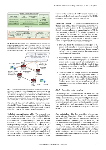
Fig. 1 – Network Management Entity Framework for TSN Switches: Cen‑
tralized Network Con iguration (CNC) is used to send and receive Con‑ 1. The CNC checks the destination address(es) of the
trol Data Traf ic (CDT), which we de ine as the signaling traf ic, e.g., the stream and consults its resource manager module
UNI information to and from the CNC and switches/sources or LLDP dis‑ for network resources available on the new stream’s
covery packets, to con igure routing segments and network resources.
path, which is computed based on the path computa‑
tion element within the CNC.
Configuration onfiguration R Reconfiguration Moduleeconfiguration Module
C
M Moduleodule
2. According to the bandwidth required for the new
R
Resource Allocation Moduleesource Allocation Module
stream (calculated at the bridge gateway for the new
C CNCNC
stream as the stream packet rate multiplied by the
SW2 3) Approval/
1) SC1 sends Stream Tx packet size and divided by the ST slot time), all links
Request Rejection CDT is
forwarded on the path are checked to see if enough bandwidth
according to
CNC logic is available for the new stream.
2) SW forwards the
Source 1 - Talker request towards
4) CDT message is the CNC 3. In the event that not enough resources are available,
forwarded to the SW3 the CNC applies the TAS recon iguration module to
source
identify the bottleneck link(s) and to check whether
SW1 the gating ratio can be increased for that speci ic traf‑
ic class whose current resource utilization will not
exhaust the resources by being added to the TAS slot
SW4 Source 2 - Listener reservation.
Fig. 2 – Centralized Model Example: Source 1 sends a CDT stream re‑ 3.1.2 Recon iguration module
quest to its gateway. The gateway forwards it to its governing CNC. The
CNC decides if the stream will be serviced according to the source UNI. The recon iguration module includes the low scheduling
All switches in the explicit path for the stream are noti ied if the stream
is accepted. Otherwise, the gateway is alerted of the rejection. Lastly, element (for our network model, the Time‑Aware Shaper
the gateway forwards it back to the source which prompts the source to (TAS) is used in the data plane), the recon iguration calcu‑
start sending data ST traf ic in the next available cycle (if approved). lus element which optimizes low registration according
to each stream’s total resource utilization and low dead‑
the network (i.e., currently utilizing network resources
(bandwidth)), and the admission control element that en‑ lines, and inally the path computation element which de‑
capsulates and decapsulates CDT headers and forwards ines the path for all streams according to the QoS con‑
the information to the necessary module/element. straint.
Global stream registration table The source streams Flow scheduling The low scheduling element cur‑
(devices/users) make a Remote Procedural Call (RPC) via rently takes the Time‑Aware Shaper into consideration.
the stream registration interface for providing informa‑ Due to the TAS’s requirements on time synchronization
tion that can be mapped as a unique tuple structure iden‑ between network components (switches, hosts, etc.), the
ti ication < , >. Upon receiving CNC follows the same principle of scheduling lows ac‑
the registration packet, i.e., Control Data Traf ic (CDT), the cording to a known timescale (initially set to be 50 s in
CNC determines whether the new stream can be accepted our network model). The CNC then passes on this time
in its stream table. To guarantee the QoS for all registered synchronization information to the TSN enabled switches
streams, admission control principles are applied to all within its domain. Any approved streams will transmit
streams according to the stream’s path, required network frames according to the time scale speci ied by the low
resources, and available resources. Fig. 2 shows an exam‑ scheduler in the CNC.
© International Telecommunication Union, 2021 17