
Page 36 - ITU Journal, Future and evolving technologies - Volume 1 (2020), Issue 1, Inaugural issue
P. 36
ITU Journal on Future and Evolving Technologies, Volume 1 (2020), Issue 1
Alternatively, the OFDM frame enables exploiting the fre‑
quency dimension, and hence, the differential modulation
technique can be also implemented using the frequency
domain scheme (see Fig. 2). According to [17], the dif‑
ferential symbols are mapped into contiguous frequency
resources of the same OFDM symbol as
⎧ , = 1,
{
,
= ⎨ −1, , , = 2, ∈ ℐ , (2)
,
{ , otherwise
⎩ −1, −1,
1 ≤ ≤ , 1 ≤ ≤ ,
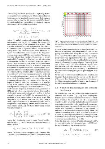
where and 2, are two reference symbols for differ‑ Fig. 3 – Mixed domain scheme in the OFDM resource grid when = 12
1,
ent purposes, and the set ℐ contains the indexes that and = 14. The yellow and blue boxes denote the reference symbols
correspond to those OFDM symbols which carry 2, . The required by the differential modulation and phase difference estimation,
irst kind of reference symbol is required for the differen‑ respectively.
tial demodulation as explained before. The second one function, where the dramatic reduction of reference sig‑
is required for the estimation of the phase difference be‑ nals can be observed. This policy mainly follows the fre‑
tween two subcarriers, consequence of the frequency‑ quency domain scheme, except for the edge subcarriers
domain mapping; see [17] for more details. We can see of the block, that follow a time domain scheme. This pro‑
that this scheme has a reduced latency and is robust posal cannot only signi icantly reduce the number of ref‑
against high Doppler shifts. Furthermore, it is reasonable erence symbols, but it is also capable of taking all advan‑
to assume that the channel responses of any two contigu‑ tages of a frequency domain scheme. Moreover, in the
ous subcarriers are similar due to the fact that the number case of time‑varying channels, only those complex sym‑
of subcarriers is always designed to be much larger than bols placed at both edge subcarriers may suffer from an
the number of taps of the channel. However, these bene‑ additional degradation, that can be easily mitigated by us‑
its come at the expense of an additional phase estimation ing some channel coding [16], [32] or spreading [33] tech‑
and compensation procedure. This additional phase com‑ niques.
ponent is very small and consequently can be neglected For the sake of conciseness and to ease the notation, the
for channels that are not very frequency‑selective. On the frequency domain scheme is the chosen one for the rest
other hand, this phase must be compensated for strong of the paper. Note that any of the presented techniques in
frequency‑selective channels. However, when diversity is the following sections can be straightforwardly adopted
exploited, only an additional reference pilot is required for both time and mixed domain schemes.
for all OFDM symbols within the coherence time ( ),
2,
which produces a negligible impact on overhead. 3.2 Multi‑user multiplexing in the constella‑
Both time and frequency domain schemes, presented in
[17], may introduce a signi icant overhead, if the number tion domain
of allocated resources is reduced ( ↓ and/or ↓). For For a single‑user case, the use of a constant modulus con‑
example, in scenarios of mMTC, the machine devices are stellation, such as DPSK [12] ‑ [15], is the only require‑
designed to send short packets of just a few bytes. The ment for the non‑coherent demodulation based on differ‑
adoption of any of the two presented schemes implies to ential detection. However, when a multi‑user scenario is
send a signi icant amount of reference symbols. Hence, considered, if we would like that all independent transmit
we propose a new mapping scheme named as mixed do‑ sources are transmitting in the same time‑frequency re‑
main scheme (see Fig. 3). Firstly, we differentially encode source (to increase the spectral ef iciency), the received
the data symbols as signals from these independent sources are summed up
and need to be conveniently separated [12]. Then, the
⎧ , = 1 choice of the constellation for each individual UE is crucial
{
= ⎨ , = 2 , 1 ≤ ≤ (3) in order to produce joint‑symbols that belong to a joint‑
−1
{ , 3 ≤ ≤
⎩ −1 −1 constellation from which it is possible to unambiguously
recover the transmitted data of all UEs.
where the denotes the resource index. Then, the differ‑ At the BS, after removing the CP and performing the DFT,
ential symbols are allocatedto thetwo‑dimensionalre‑ the received signal at the ‑th subcarrier, ‑th OFDM sym‑
source grid as
bol and ‑th antenna can be expressed as
, = ∣ ( , ) = ( ), 1 ≤ ≤ , (4)
, = ∑ √ ℎ , + , , (5)
, ,
where (•) is the resource mapping policy function. Fig. =1
3 shows a recommended example of a mapping policy 1 ≤ ≤ , 1 ≤ ≤ , 1 ≤ ≤ ,
16 © International Telecommunication Union, 2020