
Page 944 - 5G Basics - Core Network Aspects
P. 944
2 Transport aspects
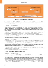
q - superframes q - superframes
Sync frame of the first of q superframes Sync frame of the first of q superframes
DS SS-X RMC . . . SS-X1 RMC . . .
Upstream RMC Upstream RMC
symbol . . . symbol
US SS-Y RMC . . . RMC . . . SS-Y1 RMC . . .
Interval under FTU-R control (≤ one superframe)
(≤ one superframe)
Vectoring feedback report (q superframes long)
Upstream
SOC R-IDLE R-VECTOR-FEEDBACK on SS-X element R-IDLE
Figure 12-11 – Vectoring feedback timing diagram
The actual duration of the VECTOR 2 stage is determined by the VCE. Upon reception of the
O-P-SYNCHRO 4 signal, the FTU-R shall complete transmission of the R-P-VECTOR 2-1 signal and transition
to the PARAMETER UPDATE stage.
12.3.3.3.7.5 O-P-SYNCHRO 3-1
The O-P-SYNCHRO 3-1 signal provides an exact time marker for transition from robust bit mapping to
normal bit mapping in the upstream direction. The O-P-SYNCHRO 3-1 signal shall have the same format,
start time and duration as the O-P-SYNCHRO 1 signal. During transmission of the O-P-SYNCHRO 3-1 signal,
the SOC is inactive.
The element of the probe sequence carried by the sync symbol of the O-P-SYNCHRO 3-1 signal shall
continue the probe sequence transmitted during the O-P-VECTOR 2 signal with no interruption.
The symbols of the O-P-SYNCHRO 3-1 signal shall use all subcarriers from the SUPPORTEDCARRIERSds
modulated as defined in clause 10.2.2.2.
The transmit PSD of the O-P-SYNCHRO 3-1 signal shall be V2PSDds.
12.3.3.3.7.6 O-P-SYNCHRO 4
The O-P-SYNCHRO 4 signal provides an exact time marker for transition from the VECTOR 2 stage to the
PARAMETER UPDATE stage. The O-P-SYNCHRO 4 signal shall have the same format, start time and duration
as the O-P-SYNCHRO 1 signal. During transmission of the O-P-SYNCHRO 4 signal, the SOC is inactive.
The element of the probe sequence carried by the sync symbol of the O-P-SYNCHRO 4 signal shall continue
the probe sequence transmitted during the VECTOR 2 stage with no interruption.
The symbols of the O-P-SYNCHRO 4 signal shall use all subcarriers from the SUPPORTEDCARRIERSds set
modulated as defined in clause 10.2.2.2.
The transmit PSD of the O-P-SYNCHRO 4 signal shall be V2PSDds.
12.3.3.3.8 Signals during PARAMETER UPDATE stage
12.3.3.3.8.1 O-P-PRM-UPDATE 1
During transmission of the O-P-PRM-UPDATE 1 signal, the FTU-O further optimizes its transmit PSD and
communicates with the FTU-R to request a downstream SNR report.
The O-P-PRM-UPDATE 1 signal shall have the same structure as the O-P-CHANNEL-DISCOVERY 1 signal and
shall consist of downstream sync symbols and initialization symbols. The SOC shall be in its active state and
use robust bit mapping. The SOC symbol repetition rate shall be set to 0 (no repetitions) and no IDS shall be
applied. The SOC quadrant scrambler shall be in free running mode. The scrambler shall be initialized at the
first SOC symbol of O-P-PRM-UPDATE 1 signal with the value communicated during the ITU-T G.994.1
934