Page 876 - 5G Basics - Core Network Aspects
P. 876
2 Transport aspects
IG _ DS 11 ( ) f is the direct channel insertion gain transfer function of line L in the
1
downstream direction over frequency f
11.4.1.2.9.1.2 Direct channel insertion gain transfer function of line L
1
The direct channel insertion gain transfer function of line L in the downstream direction over frequency f
1
is defined as:
V L 11 ( ) f
IG _ DS 11 ( ) f RX 1
N
V RX 11 ( ) f
1
where:
N
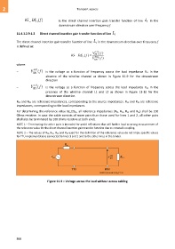
– V RX 11 ( ) f is the voltage as a function of frequency across the load impedance RL1 in the
1
absence of the wireline channel as shown in Figure 11-9 for the downstream
direction
L
– V RX 11 1 ( ) f is the voltage as a function of frequency across the load impedance RL1 in the
presence of the wireline channel L1 and L2 as shown in Figure 11-10 for the
downstream direction.
RS1 and RS2 are reference impedances, corresponding to the source impedances. RL1 and RL2 are reference
impedances, corresponding to the load impedances.
For determining the reference value IG_DS11, all reference impedances (RS1, RS2, RL1 and RL2) shall be 100
Ohms resistive. In case the cable consists of more pairs than those used for lines 1 and 2, all other pairs
shall also be terminated by 100 Ohms resistive at both ends.
NOTE 1 – Terminating the other pairs is intended for avoid reflections that will further lead to wrong measurement of
the reference value for the direct channel insertion gain transfer function due to crosstalk coupling.
NOTE 2 – The values of RS1, RS2, RL1 and RL2 used for the definition of the reference value do not imply specific values
for FTU implementations connected to lines 1 and 2 and to the other lines in the binder.
Figure 11-9 – Voltage across the load without access cabling
866

