
Page 694 - 5G Basics - Core Network Aspects
P. 694
2 Transport aspects
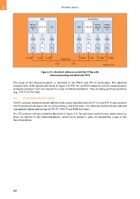
Figure 5-8 – Electrical reference model for FTTdp with
reverse powering and (derived) POTS
The scope of this Recommendation is restricted to the FTU-O and FTU-R functionality. The electrical
characteristics of the greyed-out blocks in Figure 5-8 (PSE, PE and POTS adapters) and the communication
protocol(s) between them are beyond the scope this Recommendation. They are being specified elsewhere
(e.g., ETSI TC ATTM TM6).
5.3 FTU protocol reference model
The FTU protocol reference model defined in this clause describes both the FTU-O and FTU-R, and concerns
the FTU protocol sub-layers that are all below the γ reference point. The reference model includes data and
management planes addressing the TPS-TC, PMS-TC and PMD sub-layers.
The FTU protocol reference model is illustrated in Figure 5-9. The sub-layers and reference points shown in
black are defined in this Recommendation, whilst those shown in grey are beyond the scope of this
Recommendation.
684