
Page 142 - 5G Basics - Core Network Aspects
P. 142
1 Core network aspects
individual virtual links logically. The logical separations in the redirector are done based on mappings
between virtual links to physical links at both outside and inside the VNode. It also conducts conversion of
end-user data representations, such as data packet formats, between outside and inside the VNode. It should
be noted that SDN technologies can fit well for the functionalities of redirectors.
A VNode manager controls both the programmer and the redirector in a same VNode. It implements
functions delegated by a domain controller, the primal component in managing physical resources, virtual
resources, and LINPs that are provided by a network operator.
For the sake of clarity, components in a VNode are classified logically as belonging to two planes, namely,
internal control plane and internal data plane. A VNode manager executes functions of the internal control
plane, while a programmer and a redirector execute functions for both the planes.
Several interfaces are defined for VNode system. As described in clause 18, PRI resides between the
programmer and the redirector in a VNode. In accordance to separation of internal logical planes, specifics
of PRI are defined for both the internal control and the internal data planes. For instance, Extensible Markup
Language-Remote Procedure Call (XML-RPC) is defined for the internal control plane, while physical
specifications are defined for the internal data plane. For both the planes, mac addresses of internal
components are designated.
VNode system has additional interfaces. Interface for VNode manager-to-Programmer (IF-VNP) and Interface
for VNode manager-to-Redirector (IF-VNR) are defined for the internal control plane of a VNode. IF-VNP
resides between a VNode manager and a programmer, while IF-VNR between a VNode manager and a
redirector. Outside VNodes, Interface for Domain Controller-to-VNode (IF-DCVN) is defined between a
domain controller and a VNode manager of each of the VNodes. It is used for management and control, and,
as such, is understood as containing both VMI and LMI.
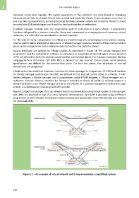
Figure I.2 depicts an example of virtual network and its implementation using VNode system. In this example,
two LINPs are provided on top of a virtual network infrastructure. Each LINP is provided using a different
programmer at some VNodes. This kind of implementation can happen when very different QoS are required
for individual LINPs.
Figure I.2 – An example of virtual network and its implementation using VNode system
132