
Page 1294 - 5G Basics - Core Network Aspects
P. 1294
2 Transport aspects
Appendix III
Example of ODUk multiplexing
(This appendix does not form an integral part of this Recommendation.)
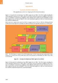
Figure III.1 illustrates the multiplexing of four ODU1 signals into an ODU2. The ODU1 signals including the
frame alignment overhead and an all-0s pattern in the OTUk overhead locations are adapted to the ODU2
clock via justification (asynchronous mapping). These adapted ODU1 signals are byte interleaved into the
OPU2 payload area, and their justification control and opportunity signals (JC, NJO) are frame interleaved
into the OPU2 overhead area.
ODU2 overhead is added after which the ODU2 is mapped into the OTU2 [or OTU2V]. OTU2 [or OTU2V]
overhead and frame alignment overhead are added to complete the signal for transport via an OTM signal.
Alignment
Client layer signal
ODU1 OPU1 OH (e.g., STM-16, ATM, GFP)
ODU1 OH
4
Alignment
Alignment
Alignment
ODU2 OPU2 OH Alignment
ODU2 OH ODU1 OH OPU1 OH (e.g., STM-16, ATM, GFP)
Client layer signal
Alignment OTU2 OH Alignment
Alignment
OPU2 OH
Alignment
OTU2 Alignment OTU2 FEC
ODU2 OH ODU1 OH OPU1 OH (e.g., STM-16, ATM, GFP)
Client layer signal
G.709-Y.1331(12)_FIII.1
NOTE – The ODU1 floats in a quarter of the OPU2 payload area. An ODU1 frame will cross multiple ODU2 frame
boundaries. A complete ODU1 frame (15296 bytes) requires the bandwidth of (15296/3808) 4.017 ODU2 frames. This
is not illustrated.
Figure III.1 – Example of multiplexing 4 ODU1 signals into an ODU2
Figure III.2 illustrates the multiplexing of two ODU0 signals into an ODU1. The ODU0 signals including the
frame alignment overhead and an all-0s pattern in the OTUk overhead locations are adapted to the ODU1
clock via justification (asynchronous mapping). These adapted ODU0 signals are byte interleaved into the
OPU1 payload area, and their justification control and opportunity signals (JC, NJO) are frame interleaved
into the OPU1 overhead area and ODU1 overhead is added.
1284