
Page 1169 - 5G Basics - Core Network Aspects
P. 1169
Transport aspects 2
Column
Row 15 16 17 18 ........... 3824
1 RES JC
2 RES JC
3 RES JC
4 PSI NJO PJO
OPUk payload (4 3808 bytes)
OPUk OH G.709-Y.1331(12)_F17-1
0 PT 0 1 2 3 4 5 6 7 8
1 JC Reserved JC
PSI 2 CSF
... RES
255
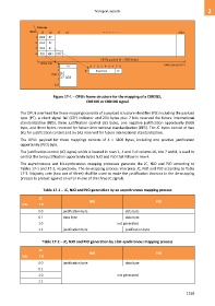
Figure 17-1 OPUk frame structure for the mapping of a CBR2G5,
CBR10G or CBR40G signal
The OPUk overhead for these mappings consists of a payload structure identifier (PSI) including the payload
type (PT), a client signal fail (CSF) indicator and 254 bytes plus 7 bits reserved for future international
standardization (RES), three justification control (JC) bytes, one negative justification opportunity (NJO)
byte, and three bytes reserved for future international standardization (RES). The JC bytes consist of two
bits for justification control and six bits reserved for future international standardization.
The OPUk payload for these mappings consists of 4 3808 bytes, including one positive justification
opportunity (PJO) byte.
The justification control (JC) signal, which is located in rows 1, 2 and 3 of column 16, bits 7 and 8, is used to
control the two justification opportunity bytes NJO and PJO that follow in row 4.
The asynchronous and bit-synchronous mapping processes generate the JC, NJO and PJO according to
Tables 17-1 and 17-2, respectively. The de-mapping process interprets JC, NJO and PJO according to Table
17-3. Majority vote (two out of three) shall be used to make the justification decision in the de-mapping
process to protect against an error in one of the three JC signals.
Table 17-1 JC, NJO and PJO generation by an asynchronous mapping process
JC
NJO PJO
bits 7 8
0 0 justification byte data byte
0 1 data byte data byte
1 0 not generated
1 1 justification byte justification byte
Table 17-2 JC, NJO and PJO generation by a bit-synchronous mapping process
JC
NJO PJO
bits 7 8
0 0 justification byte data byte
0 1
1 0 not generated
1 1
1159