
Page 1059 - 5G Basics - Core Network Aspects
P. 1059
Transport aspects 2
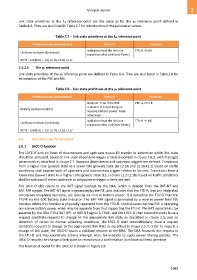
Link state primitives at the R reference point are the same as for the γR reference point defined in
Table 8-4. They are also listed in Table Z.7 for introduction of the parameter values.
Table Z.7 – Link state primitives at the R reference point
Primitive name (parameters) Content Direction
Indication that the link has FTU-R → L2+
LinkState.indicate (LinkState)
transitioned to LinkState (Note)
NOTE – LinkState {L0, L2.1N, L2.1B, L2.2}
Z.5.2.5 The γR reference point
Link state primitives at the γR reference point are defined in Table 8-4. They are also listed in Table Z.8 for
introduction of the PSE and ME.
Table Z.8 – Link state primitives at the γR reference point
Primitive name (parameters) Content Direction
Boolean: True if the PSE PSE → FTU-R
indicates it is operating on
Battery Operation (BAT)
reserve battery power. False
otherwise.
Indication that the link has FTU-R → ME
LinkState.indicate (LinkState)
transitioned to LinkState (Note)
NOTE – LinkState {L0, L2.1N, L2.1B, L2.2}
Z.6 Link state specific functions
Z.6.1 LRCC-O function
The LRCC-O acts on flows of downstream and upstream queue fill metrics to determine which link state
should be activated, based on link state dependent trigger criteria described in clause Z.6.2, with managed
parameters as described in clause Z.7. Separate downstream and upstream triggers are defined. Transitions
from a higher rate (power) state to a lower rate (power) state (L0-L2.1N and L2.1B-L2.2) based on traffic
conditions shall require both of upstream and downstream trigger criteria to be met. Transitions from a
lower rate (power) state to a higher rate (power) state (L2.1-L0 and L2.2-L2.1B) based on traffic conditions
shall be activated if either upstream or downstream trigger criteria are met.
The LRCC-O also reacts to the BAT signal sourced by the DRA, which is derived from the BAT-NT and
BAT-RPF signals. The BAT-NT signal is generated by the NT, and indicates that the FTU-R, and any integrated
emergency telephony functions, are running on reserve battery power. It is passed to the FTU-O from the
FTU-R via the EOC battery state indicator. The BAT-RPF signal is generated by a reverse power feed PSE
function where this function is physically separated from the FTU-R, and indicates that the PSE is operating
on reserve battery power which may be separate from that supporting the FTU-R. The BAT signal SHALL be
asserted by the DRA if the BAT-RPF or BAT-NT signal is TRUE, and the LRCC-O shall unconditionally issue a
request (LinkState.request) to change to the appropriate link state as described in clause Z.5, and on
detection of return to normal powering conditions, the LRCC-O shall unconditionally issue a request
(LinkState.request) to change to the appropriate link state as described in clause Z.5.In order to request a
change of link state, the LRCC-O issues a LinkState.request to the DRA. The DRA forwards this request to
the FTU-O and may coordinate actions amongst lines, for example to apply power sharing policies. The
LRCC-O records the change of link state on reception of a confirmation (LinkState.confirm) primitive.
The functional model for the LRCC-O is shown in Figure Z.6.
1049